UG-1098 ADE9000 Technical Reference Manual
Rev. 0 | Page 32 of 86
ACCESSING ON-CHIP DATA
SPI PROTOCOL OVERVIEW
The ADE9000 has a SPI-compatible interface, consisting of four
pins: SCLK, MOSI, MISO, and
SS
. The ADE9000 is always a SPI
slave; it never initiates SPI communication. The SPI interface is
compatible with 16-bit and 32-bit read/write operations. See the
Register Information section for information about the length
of each register.
Figure 41 shows the connection between the ADE9000 SPI and
a master device that contains a SPI interface.
ADE9000
SPI MASTER
MOSI
MISO
SCLK
SS
MOSI
MISO
SCK
CS
15523-041
Figure 41. Connecting the ADE9000 Slave SPI Port to a Master SPI Device
The
SS
pin is the chip select input. It is used to start the SPI
communication with the ADE9000.
There are three parts to the ADE9000 SPI protocol: first a 16-bit
command is sent, which indicates whether a read or write
operation is to be performed and which register to access. This
command is followed by the 16-bit or 32-bit data to be written,
in the case of a SPI write, or the data read from the register, in
the case of a SPI read operation. Finally, in the case of a SPI read
operation, a cyclic redundancy check (CRC) of the register data
follows, unless the address is in a region that supports burst
reading, in which case the data from the next register follows
(see the SPI Burst Read section for more information).
The
SS
input must stay low for the whole SPI transaction.
Bringing
SS
high during a data transfer operation aborts the
transfer. A new transfer can be initiated by returning the
SS
logic input low. It is not recommended to tie
SS
to ground
because the high to low transition on
SS
starts the ADE9000 SPI
transaction.
Data shifts into the device at the MOSI logic input on the falling
edge of SCLK, and the device samples the input data on the
rising edge of SCLK. Data shifts out of the ADE9000 at the
MISO logic output on the falling edge of SCLK and must be
sampled by the master device on the rising edge of SCLK. The
most significant bit of the word is shifted in and out first.
MISO has an internal weak pull-up of 100 kΩ, making the default
state of the MISO pin high. It is possible to share the SPI bus with
multiple devices, including multiple ADE9000 devices, if desired.
The ADE9000 is compatible with the following microcontroller
SPI port clock polarity and phase settings: CPOL = 0 and
CPHA = 0 (typically Mode 0), or CPOL = 1 and CPHA = 1
(typically Mode 3).
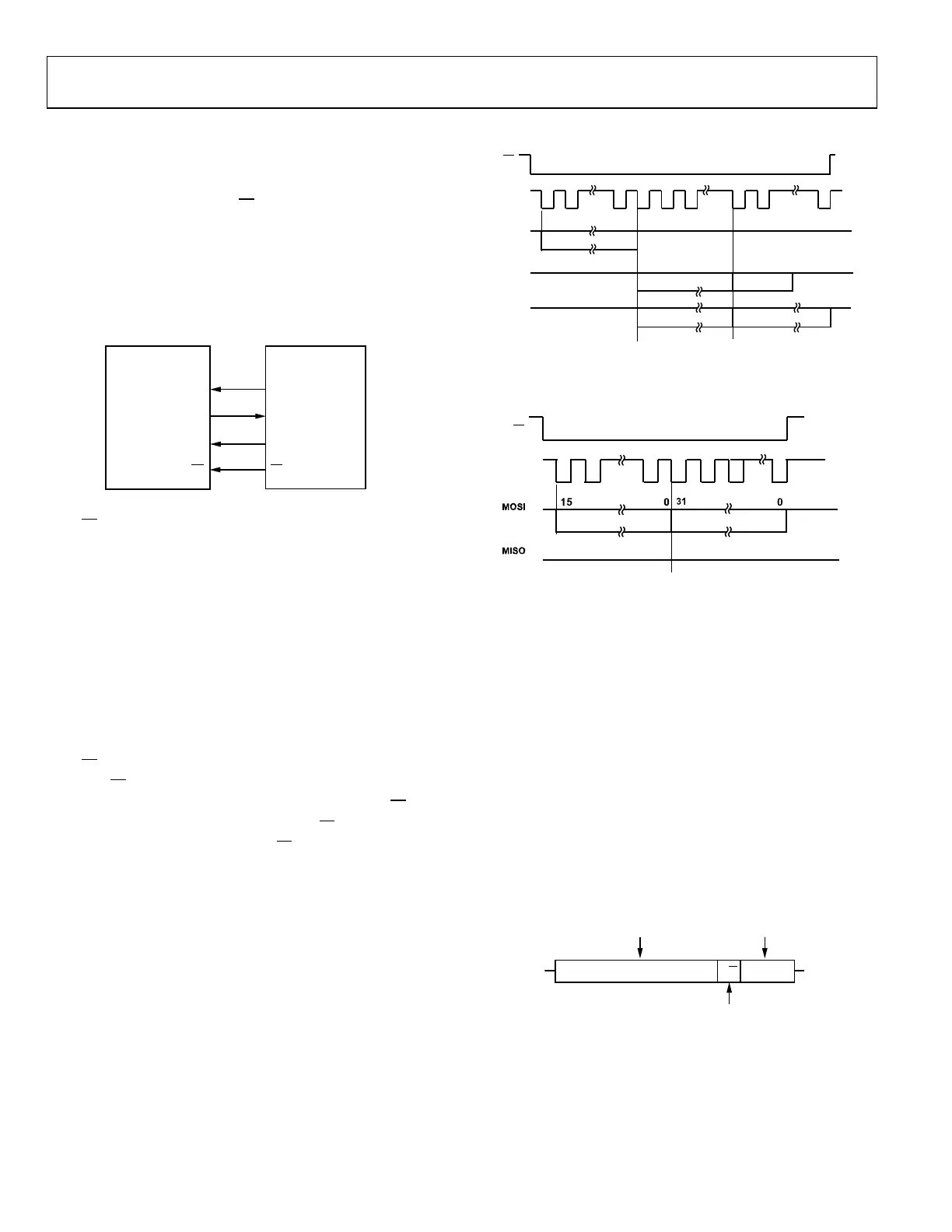
SCLK
MOSI
CMD_HDR = 0x6078
MISO
AIRMS AT 0x607 32 BITS
AIRMS AT 0x607 32 BITS BIRMS AT 0x608 32 BITS
31
SS
CRC, 16 BITS
0
15
0
15 0
31
0
MISO
31 0
BURST_EN = 0
ADDRESS 0x500 TO
ADDRESS 0x6FF
BURST_EN = 1,
ADDRESS 0x500 TO
ADDRESS 0x6FF
15523-042
Figure 42. SPI Read Protocol Example—CRC or Next Data can Follow
The default state of the MOSI pin depends on the master SPI
device. Here, it is assumed to be high (Logic 1).
SCLK
SS
CMD_HDR = 0x00B0
AVGAIN
AT 0x00B
15523-043
Figure 43. SPI Write Protocol Example
The maximum serial clock frequency supported by this
interface is 20 MHz.
The SPI read/write operation starts with a 16-bit command
(CMD_HDR), which contains the following information:
• CMD_HDR[15:4], the 12 most significant bits of the
command header, contains the address of the register
(ADDR[11:0]) to be read or written.
• CMD_HDR[3] is the bit that specifies if the current
operation is read/write. Set this bit to 1 for read and 0 for
write.
• CMD_HDR[2:0] are bits that are required for internal chip
timing and can be 1s or 0s. Note that these bits are read
back as 000 in the LAST_CMD register.
Figure 44 shows the information contained in the command
header.
15523-044
ADDRESS
TO BE ACCESSED
ADDR[11:0]
DON’T CARE
BITS
xxx[2:0]
READ = 1
WRITE = 0
15 3
R/W
2 0
Figure 44. Command Header, CMD_HDR [15:0]

 Loading...