UG-1098 ADE9000 Technical Reference Manual
Rev. 0 | Page 44 of 86
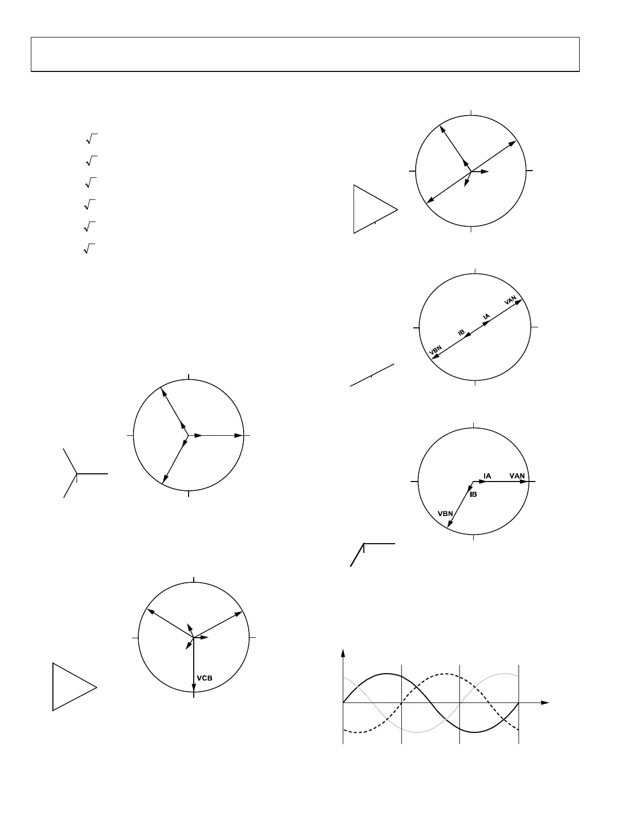
APPLYING THE ADE9000 TO DIFFERENT METERING CONFIGURATIONS
The voltage and current waveforms of a polyphase system are
defined in the following equations:
To understand how these signals relate to each other, create a
phasor diagram following a convention using lagging phase
angles. Figure 56 shows a common polyphase metering
configuration, the 4-wire wye, with v
a
, v
b
, and v
c
defined in the
previous equations. Phase B lags Phase A by 120°, and Phase C
lags Phase A by 240°. Currents are shown at a power factor of 1,
PF = 1, where θ = 0 in the i
a
, i
b
, and i
c
expressions (shown
previously), and the current is in phase with the voltage.
C
B
A
N
VAN
IA
VCN
IC
270° LAGGING
90° LAGGING
180° 0°
IB
VBN
15523-056
Figure 56. 4-Wire Wye Service Vector Diagram
The following figures show common metering configurations:
3-wire delta, 4-wire delta, and 3-wire residential and network.
The ADE9000 can also measure multiple single-phase circuits.
180°
270° LAGGING
90° LAGGING
0
°
C
B
A
VBA
VAC
IA
IC
IB
15523-057
Figure 57. 3-Wire Delta Service Vector Diagram
270° LAGGING
90° LAGGING
180°
0
°
N
C
B
A
V
AN
I
A
VCN
IC
IB
VBN
15523-058
Figure 58. 4-Wire Delta Service Vector Diagram
270° LAGGING
90° LAGGING
180°
0°
N
B
A
15523-059
Figure 59. 3-Wire Residential 1PH Service Vector Diagram
270° LAGGING
90° LAGGING
180° 0°
B
A
N
15523-060
Figure 60. 3-Wire Network Meter Vector Diagram
The phasor diagrams help to understand how the voltages and
currents are related in time. Figure 61 shows the 4-wire wye voltage
phase sequence in time, corresponding to the Figure 56 phasor
diagram and the equations for v
a
, v
b
, and v
c
provided previously.
PHASE A
VAN
PHASE B
VBN
PHASEC
VCN
15523-061
Figure 61. 4-Wire Wye, Voltage Phase Sequence in Time

 Loading...