ADE9000 Technical Reference Manual UG-1098
Rev. 0 | Page 31 of 86
V
I
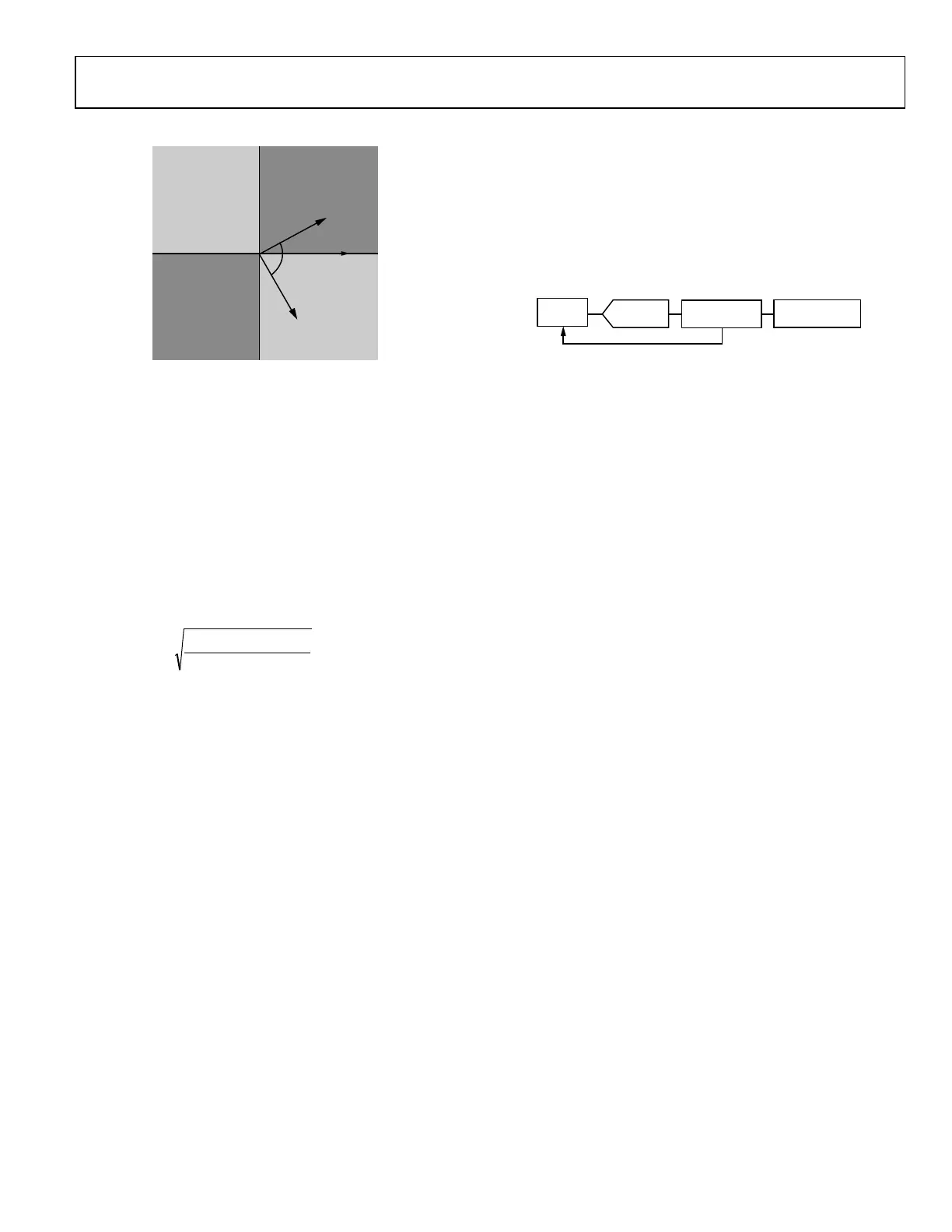
CAPACITIVE:
CURRENT LEADS
VOLTAGE
INDUCTIVE:
CURRENT LAGS
VOLTAGE
WATT
VAR
270° LAGGING
90° LAGGING
INDUCTIVE:
CURRENT LAGS
VOLTAGE
CAPACITIVE:
CURRENT LEADS
VOLTAGE
WA
TT (–)
VAR (+)
QUADRANT II
WA
TT (+)
V
AR (+)
QUADRANT I
W
A
TT (–)
V
AR (–)
QUADRANT III
W
A
TT (+)
VAR (–)
QUADRANT IV
W
A
TT(+) INDICA
TES POWER RECEIVED (IMPORTED FROM GRID)
W
ATT(–) INDIC
A
TES POWER DELIVERED (EXPORTED T
O GRID)
θ
2
= 60° PF
2
= 0.5 IND
θ
1
= –30° PF
1
= 0.866 CA
P
15523-039
Figure 39. Watt and VAR Sign for Capacitive and Inductive Loads
The power factor results is stored in 5.27 format. The highest power
factor value is 0x07FF_FFFF, which corresponds to a power factor
of 1. A power factor of −1 is stored as 0xF800_0000. To determine
the power factor from the xPF register value, use this equation:
Power Factor = APF × 2
−27
Total Harmonic Distortion
Total harmonic distortion (THD) is calculated once per second
using total and fundamental rms values, as shown in this
equation:
2
22
AIFRMS
AIFRMSAIRMS
AITHD
−
=
The THD calculation is stored in signed 5.27 format. The
highest THD value is 0x2000_0000, which corresponds to a
THD of 400%. To obtain the THD value as a percentage, use
this equation:
%THD on Current Channel A = AITHD × 2
−27
× 100%
A THD calculation is available on the IA, IB, IC, VA, VB, and VC
channels in the AITHD, BITHD, CITHD, AVTHD, BVTHD, and
CVTHD registers, respectively. Note that a THD measurement is
not available on the IN channel.
TEMPERATURE
The ADE9000 includes a temperature measurement unit that
uses a temperature sensor in conjunction with a 12-bit
successive approximation register (SAR) ADC.
TEMP
SENSOR
AVERAGE
(1,256,512,1024
TSENS_RESULT
12-BIT SAR
15523-040
Figure 40. Temperature Measurement Block Diagram
Enable the temperature sensor by setting the TEMP_EN bit in
the TEMP_CFG register. TEMP_TIME[1:0] allows 1, 256, 512,
or 1024 temperature readings to be averaged, producing a result
after 1.25 ms to 1.3 sec. A temperature acquisition cycle is
started by setting the TEMP_START bit in the TEMP_CFG
register. The result is available in the TEMP_RSLT register. The
TEMP_START bit is self clearing. Set the TEMP_START bit to
obtain a new reading. Set the TEMP_RDY bit in the MASK0
register to receive an interrupt when a new temperature
measurement is available.
The temperature reading offset and gain is measured during
production test and stored in the TEMP_TRIM register. To
convert the temperature readings in TEMP_RSLT into a
temperature in degrees Celsius, use this equation:
Temperature (°C) = TEMP_RSLT × (−TEMP_GAIN/65536) +
(TEMP_OFFSET/32)

 Loading...