UG-1098 ADE9000 Technical Reference Manual
Rev. 0 | Page 34 of 86
master sets the
SS
line high. Then, the ADE9000 stops driving
MISO and enables a 100 kΩ weak pull-up. It is recommended to
have the SCLK line idle high. An example of a SPI burst read
operation is shown in Figure 42, when BURST_EN = 1. For
other examples, see the Burst Read Waveform Buffer Samples
from SPI section.
SPI PROTOCOL CRC
The ADE9000 SPI port calculates a CRC of the data sent out on
its MOSI pin so that the integrity of the data received by the
master can be checked. The CRC of the data sent out on the
MOSI pin during the last register read is offered in a 16-bit
register, CRC_SPI, and can be appended to the SPI read data as
part of the SPI transaction.
The CRC_SPI register value is appended to the 16-/32-bit data
read from the register addressed in the CMD_HDR for the cases
in Table 20 where CRC is written (see the SPI Read section for
more information).
The CRC result can always be read from the CRC_SPI register
directly.
There is no CRC checking as part of the SPI write register
protocol. To ensure the data integrity of the SPI write operation,
read the register back to verify that the value has been written to
the ADE9000 correctly.
ADE9000 CRC Algorithm
The CRC algorithm implemented within the ADE9000 is based
on the CRC-16-CCITT algorithm. The data output on MISO is
introduced into a linear feedback shift register (LFSR)-based
generator one byte at a time, most significant byte first without bit
reversal, as shown in Figure 46 and Figure 47. The 16-bit result
is written in the CRC_SPI register.
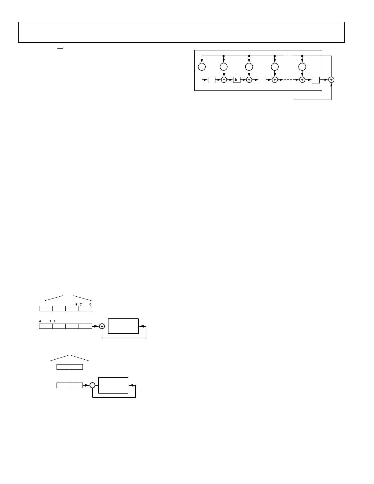
LFSR
GENERATOR
a
31
a
0
15
1623
MISO 32-BIT DATA
2431
24 3116 2315
15523-046
Figure 46. CRC Calculation of 32-Bit SPI Data
a
15
a
0
+
LFSR
GENERA
TOR
07
815
MISO 16-BIT DATA
1587
0
15523-047
Figure 47. CRC Calculation of 16-Bit SPI Data
b
0
LFSR
FB
g
0
g
1
g
2
g
15
1
g
3
b
2
b
15
a
31
, a
30
, ...,
a
2
,
a
1
, a
0
15523-048
Figure 48. LFSR Generator Used for CRC_SPI Calculation
Figure 48 shows how the LFSR works. The MISO 32-bit data
forms the [a
31
, a
30
,…, a
0
] bits used by the LFSR. Bit a
0
is Bit 24 of
the first MISO 32-bit data to enter the LFSR, and the last data to
enter the LFSR, Bit a
31
, corresponds to Bit 7 transmitted on MISO.
The formulas that govern the LFSR are as follows.
b
i
(0) = 1, where i = 0, 1, 2, …, 15, the initial state of the bits that
form the CRC. Bit b
0
is the least significant bit, and Bit b
15
is the
most significant bit.
g
i
, where i = 0, 1, 2, …, 15 are the coefficients of the generating
polynomial defined by the CRC-16-CCITT algorithm as
follows:
G(x) = x
16
+ x
12
+ x
5
+ 1 (3)
g
0
= g
5
= g
12
= 1 (4)
All other g
i
coefficients are equal to 0.
FB(j) = a
j − 1
XOR b
15
(j − 1) (5)
b
0
(j) = FB(j) AND g
0
(6)
b
i
(j) = FB(j) AND g
i
XOR b
i − 1
(j − 1), i = 1, 2, 3, …, 15 (7)
Equation 5, Equation 6, and Equation 7 must be repeated for j =
1, 2, …, 32. The value written into the CRC_SPI register contains
Bit b
i
(32), i = 0, 1, …, 15.
A similar process is followed for 16-bit data; see Figure 47 for
information about how the bits are ordered into the LFSR.
ADDITIONAL COMMUNICATION VERIFICATION
REGISTERS
The ADE9000 includes three registers that allow SPI operations to
be verified. The LAST_CMD (Address 0x4A3), LAST_DATA_16
(Address 0x4AC), and LAST_DATA_32 (Address 0x423) registers
record the received CMD_HDR and last read/transmitted data.
The LAST_DATA_16 register contains the last data read or written
during the last 16-bit transaction, and the LAST_DATA_32 register
holds the data read or written during the last 32-bit transaction.
The LAST_CMD register is updated after the CMD_HDR is
received. If a command to read the LAST_CMD, LAST_DATA_16,
or LAST_DATA_32 registers is received, these three registers
are not updated. Note that LAST_CMD[2:0] always reads back
as 000.

 Loading...