EVAL-AD9081/EVAL-AD9082/EVAL-AD9986/EVAL-AD9988 User Guide UG-1829
Rev. 0 | Page 19 of 26
ADC ANALYSIS AND DAC OUTPUT SETUP
This section explains how to use ACE for analysis of ADC data
and DPGDownloaderLite (included in ACE installation) for
sending waveforms out the DAC channels. Regardless of
whether the board view or the chip view is used, the same
procedure applies to using ACE and the DPGDownloaderLite
software.
CAPTURE AND ANALYSIS OF ADC DATA
After setting up the AD9081, AD9082, AD9986, or AD9988
using the QUICK CONFIGURATION pane in the board view,
open the ADC data analysis window by clicking the Proceed to
Analysis button in the AD9081, AD9082, AD9986, or AD9988
chip view. Set up a signal generator with a single-tone sinusoid at
1.81 GHz and ~6.5 dBm output power. Supply this signal to the
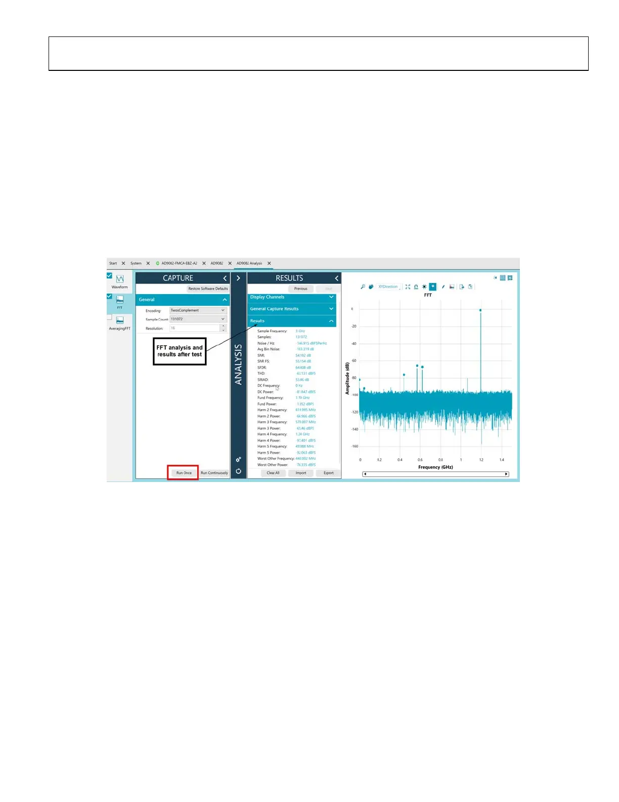
ADC0 input. Select the Wavefor m and FFT boxes on the left
side of the pane, and then click Run Once to run the FFT analysis
(see Figure 25). A graph displays, together with details of the
analysis. For optimum ADC performance, ensure that the correct
Nyquist zone is selected in the QUICK CONFIGURATION
options.
24165-023
Figure 25. FFT Analysis Window Showing a 1.81 GHz Tone Sampled at 3 GSPS

 Loading...