www.analog.com
Analog Devices
│
8
MAX30001 Evaluation System Evaluates: MAX30001
MAX30002
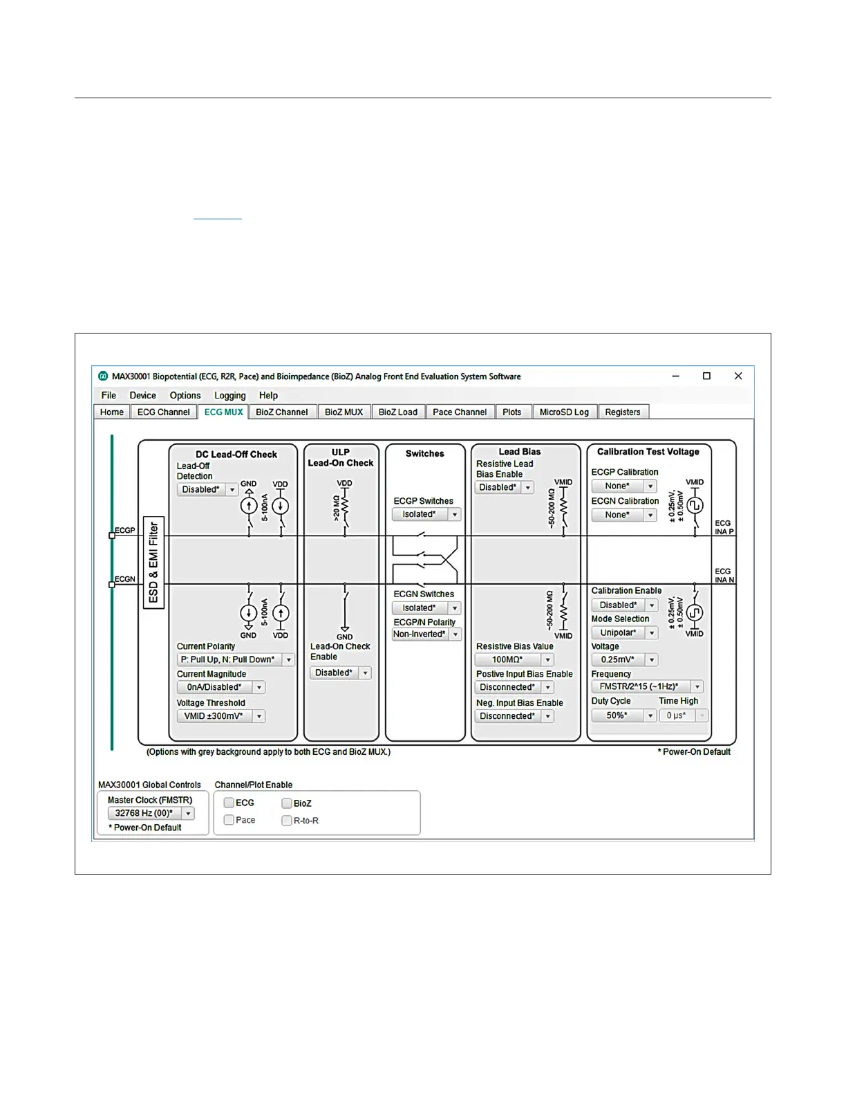
ECG MUX Tab
The ECG MUX tab (Figure 7) congures the internal ECG switches that precede the ECG ampliers and lters. Internal
calibration and verication functions of the IC are also accessible from this tab. In order to measure external ECG
signals, the ECGP Switch and ECGN Switch in the Switches block must be set to Connected. The switches should
be set to Isolated if Calibration Test Voltage is used. It is also recommended to have Resistive Lead Bias Enable
set to ECG Bias, Resistive Bias Value set to 100MΩ, Positive Input Bias Enable and Negative Input Bias Enable
set to Connected. DC Lead-O Check, ULP Lead-On Check, and Calibration Test Voltage functionalities are detailed
further in depth in the MAX30001 data sheet.
Figure 7. ECG MUX Tab
 Loading...