USER MANUAL DENTAL UNIT - QS4-451-01 / SD 300 Scandinavian
9
8.1.- Circuit box
The circuit box contains all points for connecting the dental unit to the clinic’s power supply,
as well as controls for adjusting the air and water supply. Regulator directional movement
conforms to Standard UNE20128.
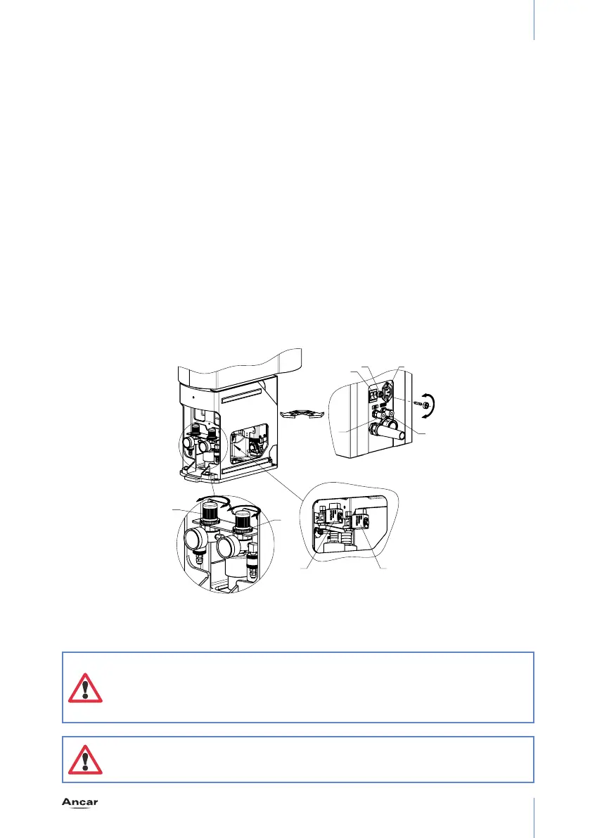
As indicated in the diagram, the front part of the chair base contains: (Fig. 4)
A. Generral power switch. Up, “on”; down, “off”. Pilot light.
B. General mains protection, placed in phase, T6,3A/250 V, time-delayed type, 5x20 mm. It
is recommended fuses replacement should be done by an authorized technician.
C. Water inlet pressure control. Fitted with a solid particle filter. Check around once a month.
D. Air inlet pressure control. Fitted with a solid particle filter. Check around once a month.
E. Water supply electro-valve.
F. Air supply electro-valve.
G. Regulated and filtered air outlet.
H. Regulated and filtered water outlet.
J. Auxiliary outlet: 230V ac / Max 50W.
Note: turning on the main switch (“A”), starts the “Autotest…” function, which
last around 3s., and is shown on the display. While this is running, the display
will light up; when it finishes, the display light turns off and the unit is set
to work mode. If an error message appears, see the section on: “Unit error
autotest. Errors”
Note: when activating the general power switch (“A”), the connection panel will
perform a function test, producing an audible beeping sound. If you do not hear
this sound, switch off the unit and contact your technical service provider.
'
&
$
%
*
+
-
(
)
Fig. 4