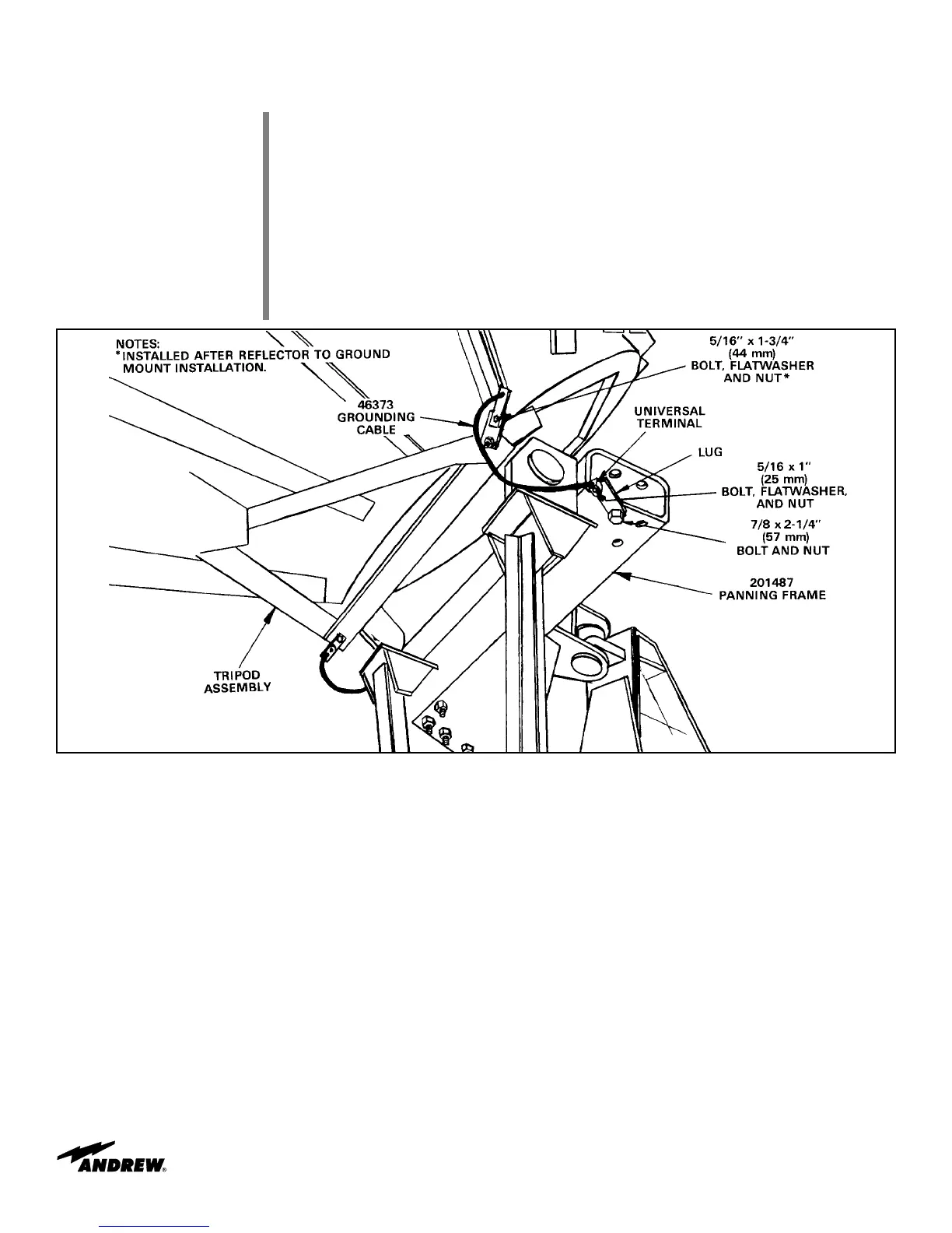
Refer to Figure 69. Attach lugs to universal terminals at each end of 46373 grounding
cable as shown, using 5/16 by 1 inch (25 mm) bolts, flat washers and nuts. Attach cable
to available hole in panning frame, using 7/8 by 2-1/4 inch (57 mm) bolt and nut. Attach
other end of cable to existing 5/8 by 2 inch (51 mm) bolt on tripod as shown. Attach sec-
ond grounding cable to other side of elevation axis/panning frame assembly.
Attach foundation grounding cable connectors to each mount leg. Cable attachment and
foundation grounding system to be installed per local code.
Securely tighten all remaining ground mount/jack assembly hardware per A-325 hardware
tensioning procedure.
Step 2
Step 3
Step 4
53
Installation Procedures
Figure 69
 Loading...