Subreflector
Assembly and
Adjustment
Step 1
Step 2
50
Installation Procedures
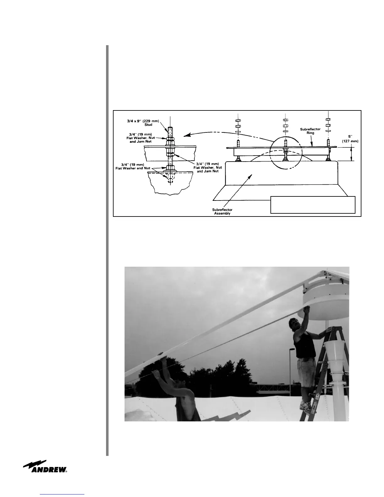
Install subreflector subassembly to subreflector ring by inserting studs on subassembly
into adjustment stud mounting holes as shown in Figure 65.
• Use 3/4 in (19 mm) flatwasher, nut and jam nut
Figure 66
Figure 65
Refer to Figure 66. Measure and note the distance between either outermost angle clip
bolt head and the subreflector rim. Obtain the corresponding measurements from the
remaining subreflector struts, and adjust the subreflector mounting hardware (4 places)
to achieve a maximum differential of 1/16 inch.
NOTE: 5” (127mm) dimension shown is a
starting reference only. Dimension will
vary after adjustments are complete.
 Loading...