Azimuth
Jackscrew
Assembly
Step 1
Step 2
Mount Assembly
Step 1
Step 2
25
Installation Procedures
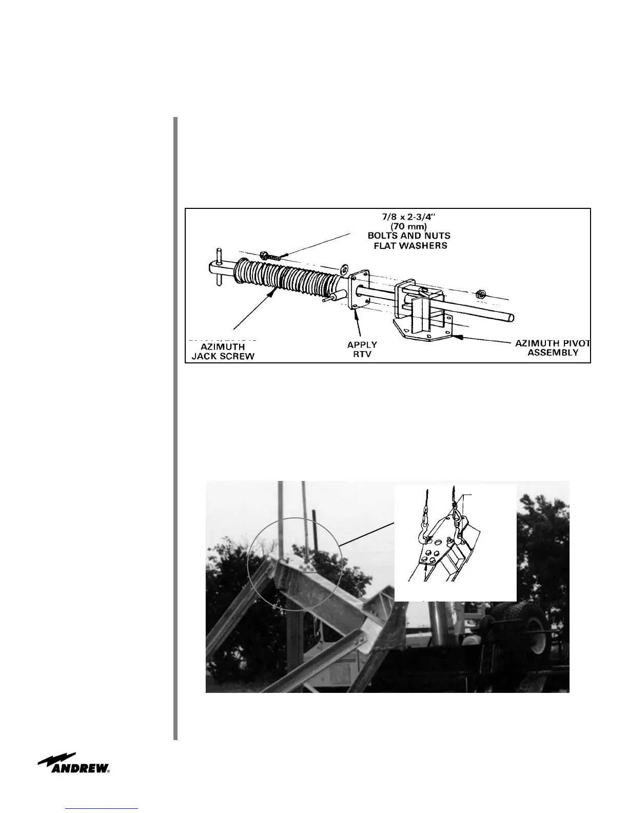
Insert 221923/223180 azimuth jackscrew tube into 221738 azimuth pivot assembly as
shown in Figure 29. Insert jack carefully to prevent scratching jackscrew tube. Note:
Ensure jackscrew assembly remains fully retracted at this time.
Figure 29
Apply RTV to flange surface as shown in Figure 29. Fasten jack to pivot using 7/8 x 2-
3/4 in (70 mm) bolts and nuts. Mounting hardware is included with corresponding jack
assembly hardware kit.
Attach shackles to beam assembly as shown in Figure 30.
221923/223180
Figure 30
Lift support legs to azimuth beam assembly.
221738
Shackles
200088A
Joint Assembly
 Loading...