Step 7
Step 8
Step 9
56
Move the antenna in azimuth to obtain a null, then move ± in elevation to obtain a large
peak signal. If not, move the antenna in the opposite azimuth direction through the peak
and again move ± in elevation to obtain a large peak signal. If a larger peak is not
found, you were on the main lobe.
NOTE: The following explanation for polarization adjustment addresses the special case
of full transponder signals. Some applications may include partial transponder signals.
If your antenna is equipped with a linear polarizer, the antenna is aligned in azimuth and
elevation (signal maximized) and 24 transponder signals (12 horizontal and 12 vertical)
are noted, the polarization adjustment is set incorrectly and must be modified. If 12
transponder signals are noted, they may or may not be the properly polarized signals.
Therefore 24 transponder signals must be visually noted in order to determine the prop-
er polarization setting.
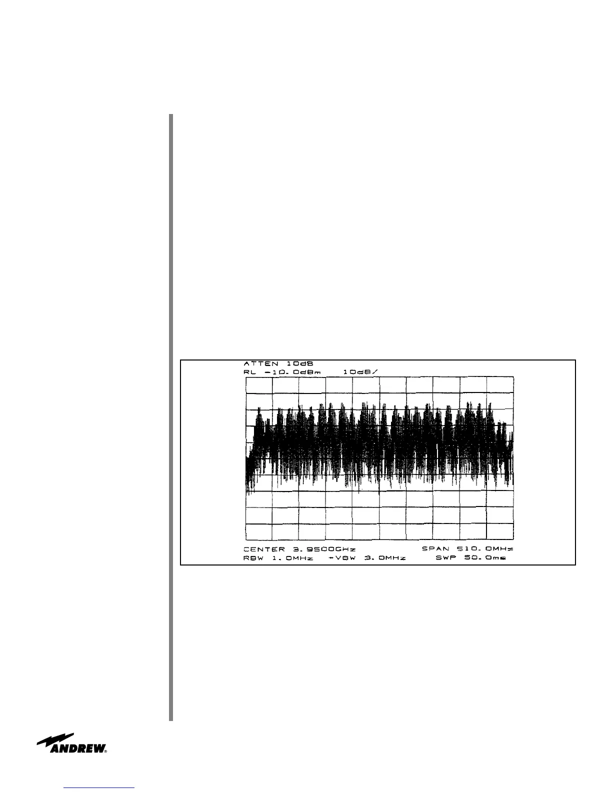
Rotate the feed assembly clockwise until 24 transponder signals are noted and of
approximately equal amplitude.
NOTE: It is more accurate and visually easier to minimize the alternate set of transpon-
der signals rather than maximizing the transponder of interest.
Figure 4-3: Polarization at 45 degrees from Optimum Setting
Operation
 Loading...