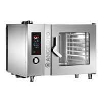
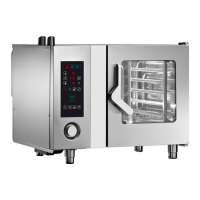
Do you have a question about the Angelo Po FX101E2 and is the answer not in the manual?
Diagrams showing electrical and gas connections for the combi oven.
Specifications for water quality required for optimal appliance performance.
Explains the system's function when the motorised valve is open.
Explains the system's function when the motorised valve is closed.
Describes the process of cooling down and condensing steam within the oven.
Details the process by which the oven generates steam.
Overview of the electronic boards and their arrangement in Level 3 models.
How to access and use the oven's service menu for diagnostics and settings.
Procedures to follow after replacing specific electronic components.
Details on the inverter's role, operation, and troubleshooting alarm codes.
Overview of the electronic boards and their arrangement in Level 2 models.
Detailed description of fuses used in the FX series ovens.
Explains the general principles of the FX oven's gas system operation.
Illustrates the power output levels and their relation to fan speed in the gas system.
Identifies and describes the various components of the oven's gas system.
Details the step-by-step operational logic of the blower and combustion control boards.
Guides the user through the gas system setup and testing procedure.
Lists the recommended CO2 and CO values for optimal combustion.
Troubleshooting guide for gas alarms and burner issues.
Steps for converting the oven from natural gas to propane.
Specific steps for performing a gas test on Level 2 ovens.
Requirements and procedures for annual gas flue analysis.
Describes the components and workings of the Level 3 washing circuit.
Step-by-step guide for verifying the functionality of the washing circuit pumps.
Procedures to follow if a washing cycle is interrupted unexpectedly.
Table detailing washing cycle alarms and their corresponding solutions.
Table showing detergent, sanitizer, and water consumption for different cleaning cycles.
Explains the warning and blockage screens related to oven cleaning status.
Information on the warning screen indicating the need for descaling.
Details the components and operation of the washing circuit in Level 2 ovens.
Step-by-step instructions for replacing the encoder component.
Guides on motor replacement, including shaft sealing system assembly.
Instructions for replacing the micro-switch located on the oven door.
Steps for safely disassembling the oven door's inner glass frame.
Details on the cooling fans and air intake slots for component protection.
Procedures for adjusting the oven door for proper sealing and alignment.
Steps for replacing the internal temperature probe (core probe).
Instructions for replacing the humidity sensor probe inside the cooking chamber.
Procedure for replacing the halogen lamp, including fuse details.
Detailed steps for dismantling and reassembling the oven door lock mechanism.
Instructions for replacing the spark plug and its associated gasket.
Steps for replacing the blower fan, including diaphragm checks.
Guide for replacing CPU and LCD display boards in Level 3 ovens.
Instructions for replacing CPU boards, differentiating between 1st and 2nd versions.
Steps for adjusting the oven for roll-in installation.
Checklist of maintenance tasks and their recommended frequency.
Explains alarms related to water supply issues and pressure.
Addresses alarms concerning gas supply, pressure, or flame detection failures.
Details alarms related to the oven door opening or closure status.
Alarms indicating cleaning cycle issues or warnings.
Troubleshooting alarms for cooking chamber, core, and steam probes.
Alarms related to electronic board failures or communication errors.
Alarms indicating configuration errors, missed tests, or valve issues.
Alarms related to general electronic circuit board diagnostics and protections.
| Category | Oven |
|---|---|
| Model | FX101E2 |
| Capacity | 10 x 1/1 GN |
| Temperature range | 30 - 300 °C |
| Control system | Touchscreen |
| Type | Electric Combi Oven |


