6
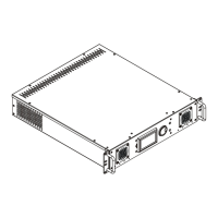
4. Conguration of terminals
DMX output DMX input
XLR mounting sockets (rear view) XLR mounting plugs (rear view)
1 – Shield 2 - Signal (-) 3 - Signal (+) 4 – Not connected 5 – Not connected
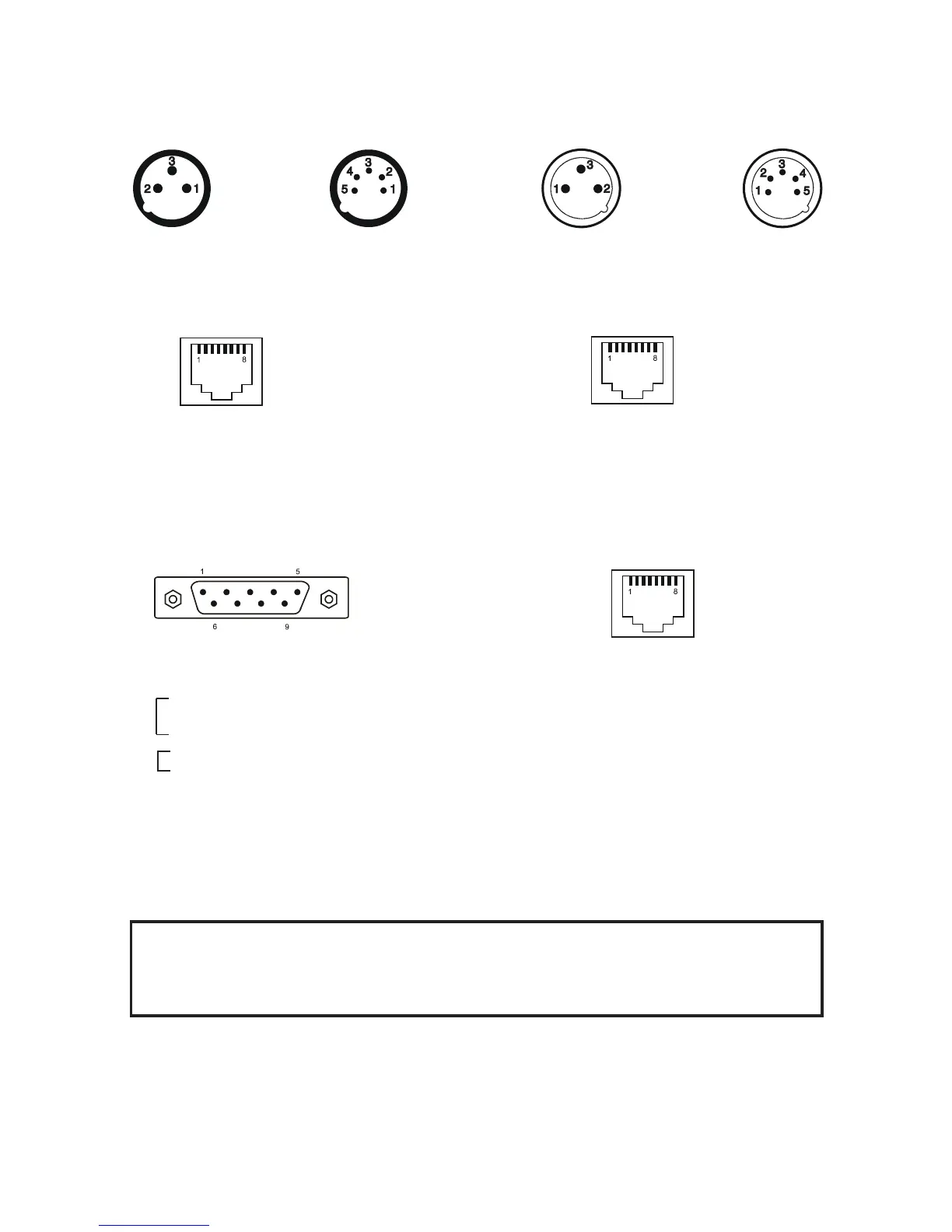
DyNet input Ethernet
RJ 45 female (rear view) RJ 45 female (rear view)
Control port (RS232) LED output zone
DE-9 (male) RJ 45 female (rear view)
5. Installation
5.1 Connection to the mains
CAUTION!
These servicing instructions are for use by qualied service personnel only. To
reduce the risk of electric shock do not perform any servicing other than that con-
tained in the operating instructions unless you are qualied to do so.
The ArcPower 384 Rack Mount is equipped with auto-switching power supply that automatically adjusts to any
50/60Hz AC power source from 100-240 Volts.
The fixture is equipped the cord & plug QP 02 but you can use the following plugs:
P620,24W47,14W49,24W49,26W81,HBL4720C,HBL2311, HBL2321,HBL2811 and the cords SJT or 22326.
Pin 1: Not connected Pin 5: Not connected
Pin 2: +12V Pin 6: Data +
Pin 3: Not connected Pin 7: Data -
Pin 4: Not connected Pin 8: GND
Pin 1: Not connected
Pin 2: Received Data
Pin 3: Transmitted Data
Pin 4:
Pin 5: Signal Ground
Pin 6:
Pin 7:
Pin 8:
Pin 9: Not connected
Pin 1: Red LEDs + Pin 5: Red LEDs -
Pin 2: Green LEDs + Pin 6: Green LEDs -
Pin 3: Blue LEDs + Pin 7: Blue LEDs -
Pin 4: White LEDs + Pin 8: White LED -
Pin 1: TX+ Pin 5: Not connected
Pin 2: TX- Pin 6: RX-
Pin 3: RX+ Pin 7: Not connected
Pin 4: Not connected Pin 8: Not connected