7-7 Signal Generator Replacement Chapter 7 — Assembly Replacement
7-8 PN: 10580-00324 Rev. N S412E MM
7-7 Signal Generator Replacement
This procedure provides instructions for removing and replacing the Signal Generator PCB Assembly. This
procedure requires a Cable Removal Tool, Anritsu part number 783-1399, to remove a co-axial cable connected
between the Main PCB and Signal Generator PCB.
1. Open the case as described in Section 7-2 “Opening the S412E Case”.
2. Remove the PCB Assembly from the front panel as described in Section 7-3 “PCB Assembly
Replacement”.
3. Remove the SPA board as described in Section 7-4 “SPA Assembly Replacement”.
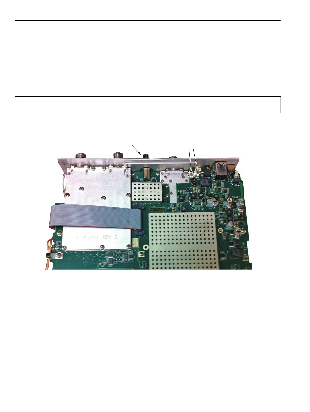
4. Remove the castle nut on the Audio In connector on the top panel and the two screws shown in Figure 4.
Note
The SPA board cables, connector and the DSP board do not need to be removed when replacing the
Signal Generator PCB Assembly. Remove the screws and move the SPA board to the side.
Figure 7-9. Remove Castle Nut and Two Screws
Remove 2 screws
Remove castle nut