58
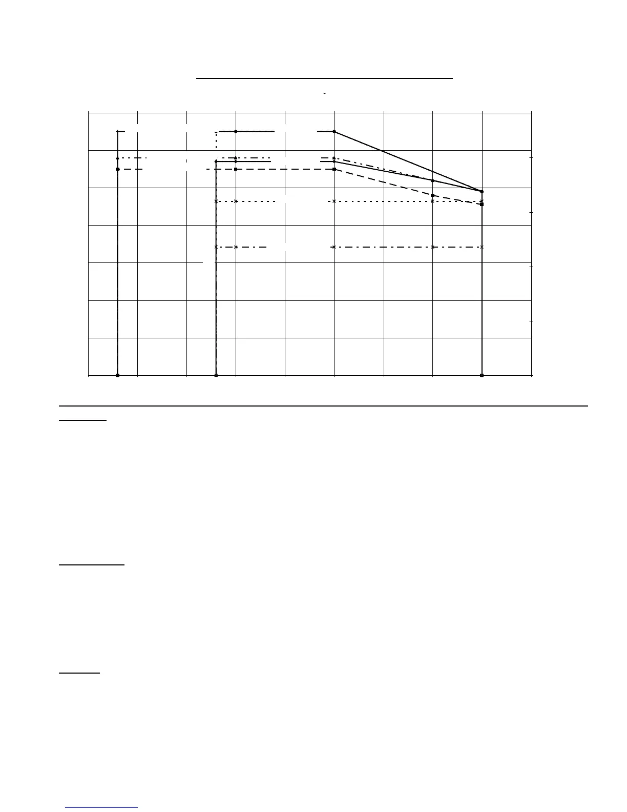
PRESSURE & TEMPERATURE CAPABILITY
-20
0
50
100
150
200
250
300
350
-150 -100 -50 0 50 100 150 200 250 300
Tem
erature
F
Pressure
si
0
5
10
15
20
-100 -75 -45 10 40 65 95 120 150
em
era
ure
NSI 150
DI
6&8"
ANSI 150
HAST B&C
6&8"
COLD LIMIT FOR ALL DI
NSI 300
DI
8"
ISO PN16
DI
6&8"
ANSI 150
316SS
6&8"
ANSI 300
316SS & HAST B&C
6&8"
JIS 10k
/cm2
DI
6&8"
CASING
• Meets ANSI B73.3 or ISO 2858 or JIS B8313 foot and flange position and size standard
• Self-venting and top centerline discharge.
• Material: One piece solid ductile iron casing, lined with rotomolded ETFE fluoropolymer 1/8 in. (3 mm) min.
Optional (ANSI models, only): Alloy casing in 316 SS, Hastelloy® B or Hastelloy® C (no lining).
• Foot supported for maximum resistance to distortion from pipe loads.
• Pure sintered silicon carbide thrust ring integral with front shaft support.
• Flanges: ANSI/ASME B16.5 Class 150 or ISO 2084 Class NP 16 flanges standard.
Optional: ANSI/ASME B16.5 Class 300 on alloy casings, only.
• Casing drain connection standard.
IMPELLER
• Closed type, one piece construction
• Manufactured with carbon fiber filled ETFE fluoropolymer.
• Magnets fully encapsulated by ETFE fluoropolymer.
• Replaceable, press fit main bushing, either carbon/graphite or sintered silicon carbide.
• Replaceable, mouth ring, either carbon fiber filled PTFE or sintered silicon carbide.
• Optional glass fiber filled PFA.
SHAFT
• Non-rotating, 1.25" (32 mm) diameter.
• One piece, solid construction, sintered silicon carbide (SiC).
• Fully supported at both ends utilizing front shaft support and containment shell.
• Axial groove for improved lubrication and particulate bypass. U.S. Patented.