7
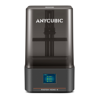
(3) Fig.4, insert “Hotend” connector to the middle port (14 pins).
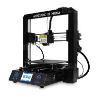
(4) Fig.5, insert “X/Z motors&endstops” connector to the upper port (16 pins).
(Figure 4) (Figure 5)
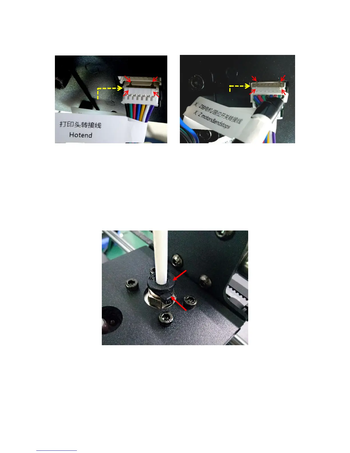
(5) Fig. 6, customers may notice there is a piece of zip tie attached just below the plastic ring
of the quick connector. Do not cut it off. Only cut this zip tie when swapping or repairing
a malfunction hotend, because it needs to push down the plastic ring and pull out the
Teflon tubing.
4. Spool holder and filament sensor
(1) As shown in Fig. 7, assemble the spool holder and tighten 4 pairs of screw and nuts at
the lower corner. (The color and shape of the spool holder might be slightly different from this
pircture)