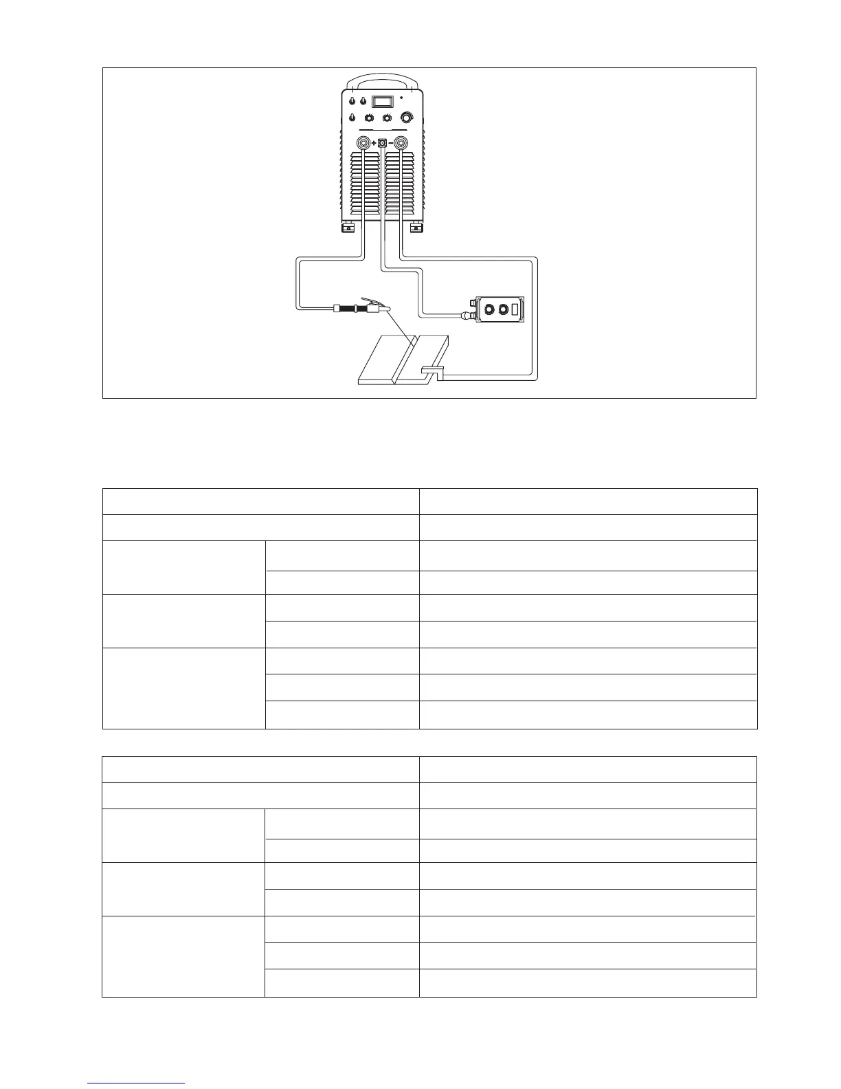
Fig. 6-5-1: Installation
Input power supply cable installation
Please note the size of fuse and circuit breaker in the table below are for reference only.
Single voltage
Model
Power supply
28
45
80
100
6
50
6
400II
3 phase, AC220V±10%, 50/60Hz
Min. capacity (KVA)
Power network
Generator
Fuse
Circuit breaker
Input cable
Output cable
Protective GND wire
Min. cable size (mm )
2
Input protection (A)
Table 6-5-1: Input power supply cable installation- single voltage AC220V
Model
Power supply
3 phase, AC380V/400V/415V/440V/525V ±10%, 50/60Hz
28
45
50
63
4
50
4
400II
Min. capacity (KVA)
Power network
Generator
Fuse
Circuit breaker
Input cable
Output cable
Protective GND wire
Min. cable size (mm )
2
Input protection (A)
Table 6-5-2: Input power supply cable installation- single voltage AC380V/400V/415V/440V/525V
A/ V
4
3
2
1
5 6
7
8
9
10
4
3
2
1
5 6
7
8
9
10
REMOTE
A
V
PROTEC TION
STA RTCU RRENT
ARC FO RCE
M
S
L
ARC LE NGT H
Inverter D C A r c W e lding Mac h ine
ARC400
Ⅱ
PANEL
W EL DING C URR ENT
WELDING CURRENT
ARC FORCE/D ECAY TMI E
A
9
7
4
3
2
8
6
5
10
1
3
9
4
2
7
10
8
65
1
35
 Loading...