50
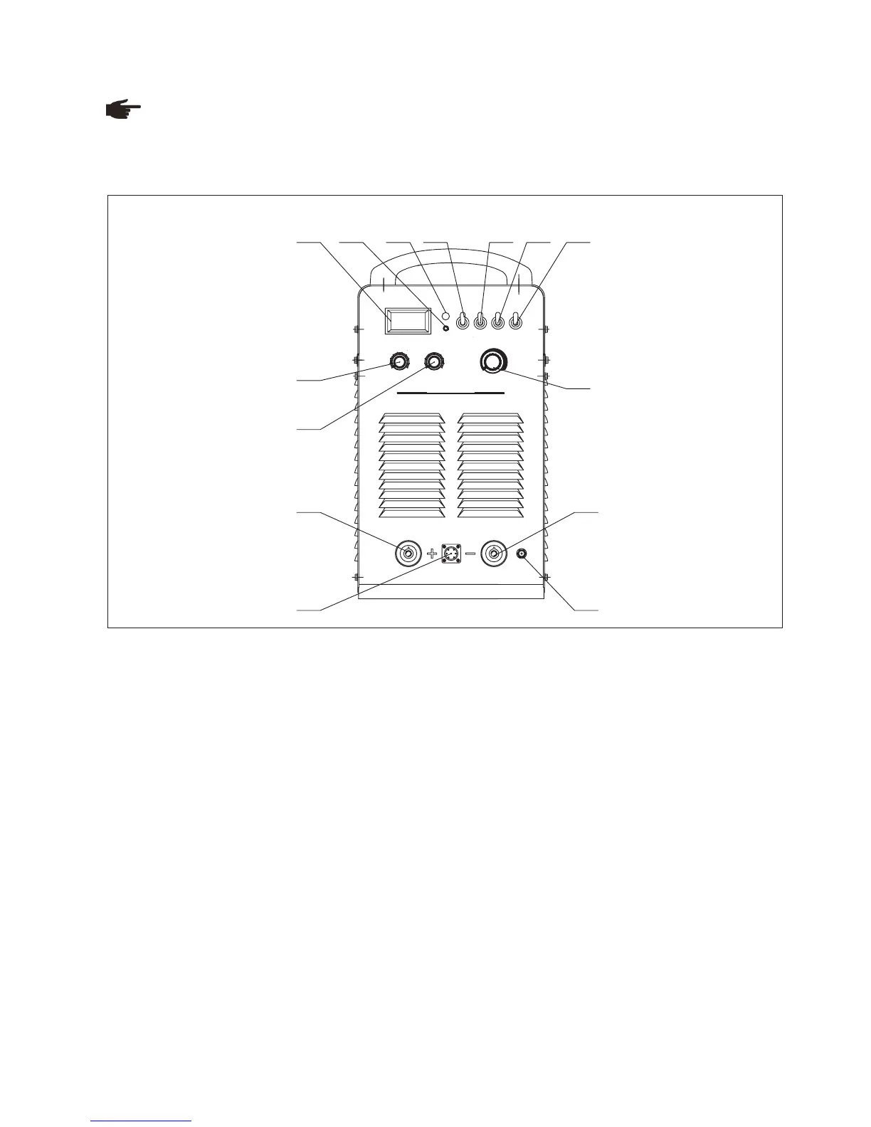
Front panel
Fig. 8-3-1: Front panel
1. Amp/Volt displayer
When display mode switch indicates to “Amp”:
- LCD displays preset current value, Min. current is 20A;
- LCD displays real welding current during working.
When display mode switch indicates to “Volt”, LCD displays voltage between output terminals of welding machine.
2. Protection indicator
Welding machine will automatically stop working when it is overheat, and the indicator will light up.
3. Default phase indicator
Indicator indicates when power source is default phase.
4. “Amp/Volt” displayer mode selection switch
5. ”SMAW/TIG” switch
When it is indicated to “SMAW”, the machine is to work on SMAW;
When it is on “TIG”, the machine is to work on TIG.
6. 4-step/ 2-step switch (used in TIG welding)
Press this button to switch between 2-step and 4-step operation mode, the indicator will lights up accordingly.
8-3 Interface
Note! You may find that your machine has certain functions or some parameters that are not described in this
operating manual. Also, certain illustrations may be very slightly different from the actual controls on your machine.
However, these controls function in exactly the same way.
Torch operation mode:
Legend:
9
A/V
5 6
7
8
9
10
4
3
2
11
2
3
4
10
8
7
65
TIG
SMAW
4-STEP
2-STEP
REMOTE
PANEL
WELDING C U RRENT
PROT ECRION
START CURREN T
Inverter MM A /TIG A r c We ld ing M a chine
V
A
TIG400
ARC FO RC E/DOWN -SLOPE T IME
2 3 4 5 6 7
8
9
1
10
11
12
13
14
 Loading...