23
5-ARC1000/1250
5-1 System components
Please refer to “ARC315/400/500/630” the relevant “4-1 System components” in details.
5-2 Basic equipments for welding
Please refer to “ARC315/400/500/630” the relevant “4-2 Basic equipments for welding” in details.
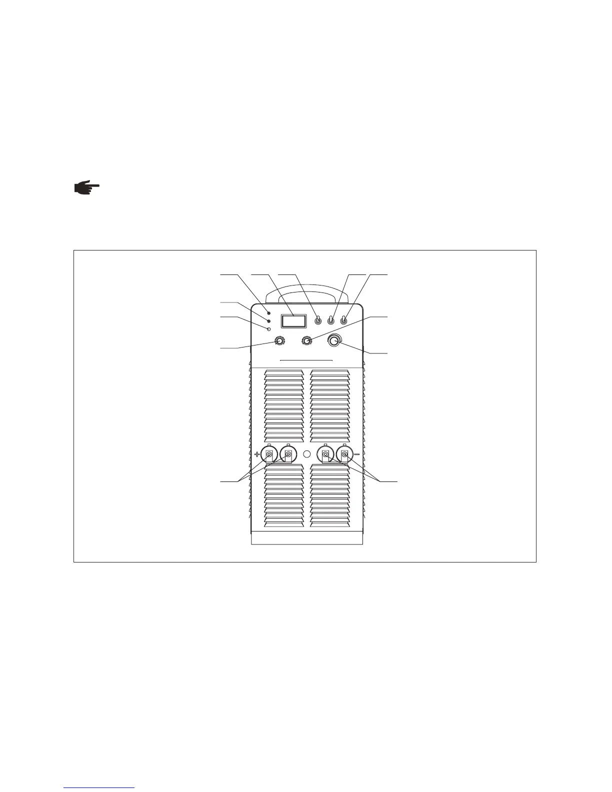
5-3 Interface
Note! You may find that your machine has certain functions or some parameters that are not described in this
operating manual. Also, certain illustrations may be very slightly different from the actual controls on your machine.
However, these controls function in exactly the same way.
Front panel
1.Over heat indicator
Welding machine will automatically stop working when it is overheat, and the indicator will light up.
2.Fault indicator
Welding machine will automatically stop working when it is in fault, and the indicator will light up.
3.Default phase indicator
Indicator indicates when power source is default phase.
4.Amp/Volt displayer
When display mode switch indicates to “Amp”:
-LCD displays preset current value, Min. current is 20A;
-LCD displays real welding current during working.
When display mode switch indicates to “Volt”, LCD displays voltage between output terminals of welding machine.
5.“Amp/Volt” displayer mode selection switch
Fig. 5-3-1: Front panel
A/V
4
3
2
1
5
6
7
8
9
10
4
3
2
1
5
6
7
8
9
10
OVER-HEAT
FAULT
DEFAULT
PHASE
A
V
SMAW
GOUGING
ARC LENGTH
L
M
S
Inverter DC Ar c Weld ing Ma chine
ARC1000
ARC FO RCE CURR ENT
ARC STARTING CURRENT
WELDING CURRENT
2
3
8
11 12
1 4 5 76
9
10
 Loading...