62
6.“Amp/Volt” displayer mode selection switch
7.SMAW / TIG / Gouging switch
Transfer among SMAW / TIG / Gouging.
8.4-step/ 2-step switch (used in TIG welding)
Press this button to switch between 2-step and 4-step operation mode, the indicator will lights up accordingly.
For torch operation mode, please refer to “TIG315/400/500/630” the relevant “8-3 Interface” in details
9.Arc length switch
-In SMAW mode:
Long: output cable length is more than 25m, less than 40m;
Short: output cable length is less than 10m;
Middle: output cable length is more than 10m, less than 25m.
-It is on “Long” position when in air arc gouging welding.
10.“Arc force current” regulation knob
It is used to adjust arc force current under SMAW.
When welding, short circuit between wire and work piece may occur because of operation or droplet transfer. In
order to avoid short circuit or wire stick, when arc voltage is low, increase current to shorten the droplet transfer
time.
11.“Welding current” regulation knob
It is used to adjust welding current on panel control mode.
Preset proper welding current according to work piece thickness, groove shapes, welding position, wire diameter,
etc. Welding current decides welding seam depth and wire molten rates.
12.Positive output terminal (+)
It is used to connect with electrode holder via welding cable on SMAW mode, connect to work piece via ground
cable on TIG mode, connect to the gouging torch on Gouging.
13.Negative output terminal (-)
It is connected to work piece via ground cable on SMAW mode and Gouging, connected to TIG torch welding cable
on TIG mode.
14.Gas outlet
Connect to gas hose of TIG torch.
15.Torch control socket
On TIG mode, connect control cable of the torch.
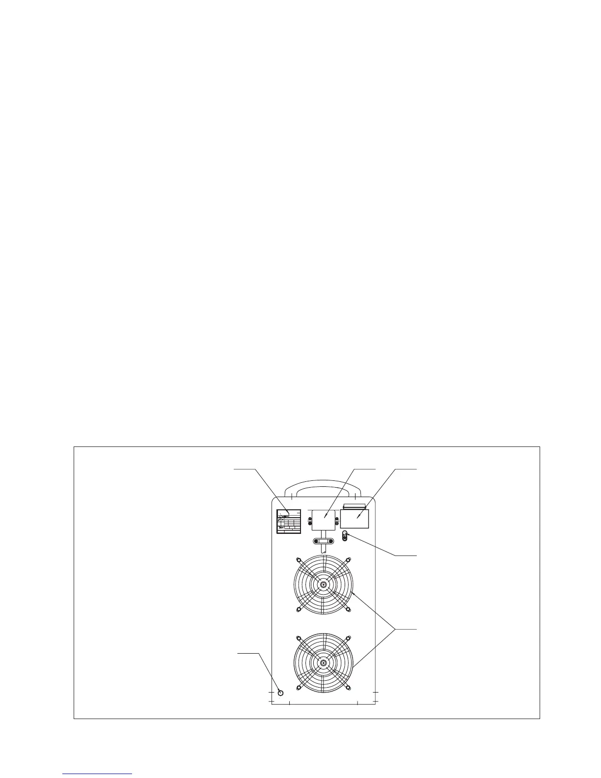
Rear panel
Fig. 9-3-2: Rear panel
3
~
f
2
f
1
MODEL No.
MA DE I N
X
U
2
I
2
100%
44V
STANDARD: GB1 5579.1-2004
TIG1000
60A/ 22.4V~100 0A/44 V
U
0
=79V
1000 A
U
1
=415V I
1max
=76A I
1eff
=76A
3
~
50Hz
PROTECTIONDE GREE:IP23S
INSULATION DE GRE E: H
12
3
4
5
6
 Loading...