POS MV V4 User Guide
Installation
Copyright © Applanix Corporation, 2009
2-19
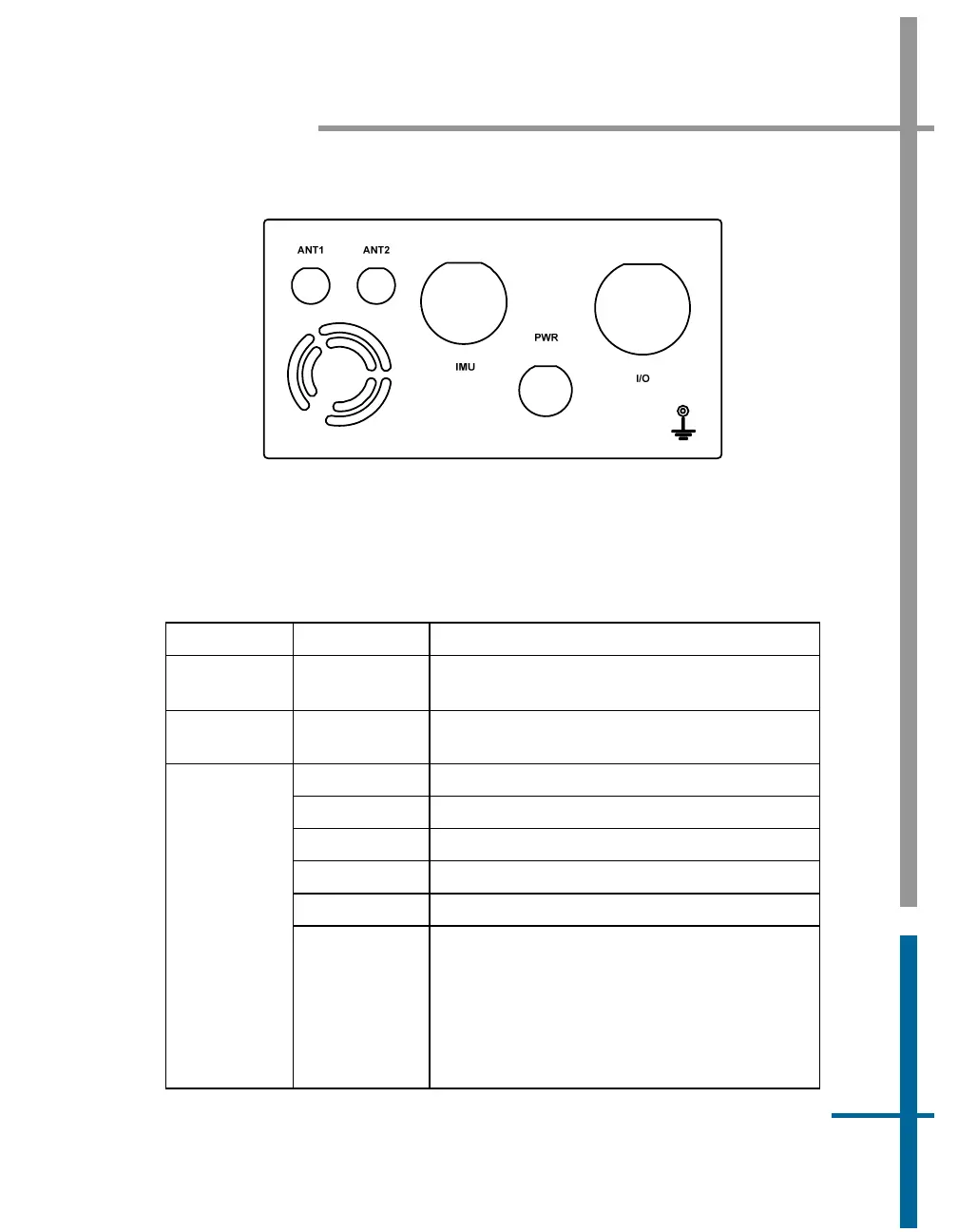
Figure 7: PCS Rear Panel - POS MV V4-1
Use
Table 3 as a guide when making cable connections to the PCS rear
panel.
Table 3: Connector/Cable Summary - POS MV V4-1
Connector Port Description
PWR Connects to a power converter; see page 2-
4 for details
IMU
• RS-422 serial I/O port
• Supplies dc power and data to/from IMU
COM (1) RS-232 Serial I/O port (digital)
COM (2) RS-232 Serial I/O port (digital)
COM (3) RS-232 Serial I/O port (digital)
COM (4) RS-232 Serial I/O port (digital)
COM (5) RS-232 Serial I/O port (digital)
I/O
GNSS 1/2
(GNSS 1 =
primary)
(GNSS 2 =
secondary)
• RS-232 Serial I/O port (digital)
• Primary GNSS receiver software upgrade
- contact Applanix Customer Support for
details
• Secondary GNSS receiver software
upgrade - contact Applanix Customer
Support for details