POS MV V4 User Guide
Installation
Copyright © Applanix Corporation, 2009
2-36
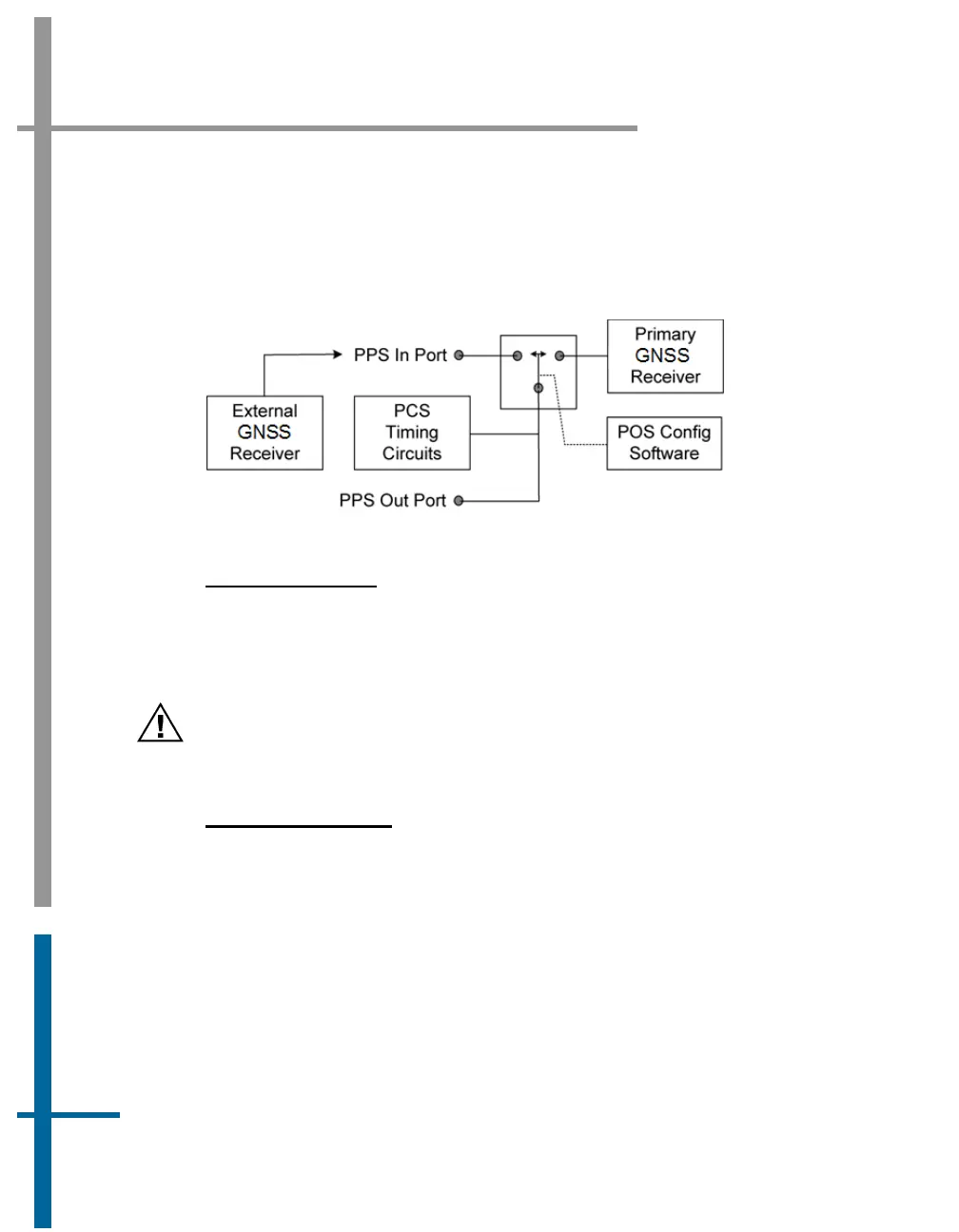
the external GNSS option is enabled through the POSConfig menu selection
in MV-POSView (refer to the
Manage Multiple Configurations description on
page 4-40).
Figure 14 provides a functional diagram.
Figure 14: PPS Port Signal Sources - Functional Diagram
P
HYSICAL INTERFACE
A cable must be constructed and installed to couple the 1PPS signals;
Table 5, page 2-23 (POS MV V4-1) or Table 2, page 2-15 (POS MV V4)
provides connector pin assignments and mapping.
The PPS output port is an active circuit. Ensure that an ‘input
signal’ is NOT connected to the PPS output port, otherwise
damage may result.
O
UTPUT DATA FORMAT
The 1PPS signal (input or output) is an active ‘LOW’ TTL level strobe that
occurs at a 1 Hz rate. The leading edge of the strobe is coincident with the
exact GNSS second. The corresponding GPS Time message that specifies
the UTC time of the 1PPS may be selected for output from a National Marine
Electronics Association (NMEA) port. Refer to the
GNSS Timing Basics
description starting on page
H-3.