POS MV V4 User Guide
Installation
Copyright © Applanix Corporation, 2009
2-21
All cables are labelled and in some cases have different terminations on each
end. Route cables away from sources of electrical noise and protect from
physical damage. Secure cables to permanent supports that are close to
cable connectors to provide relief from shock and vibration. Coil and stow
excess cable and secure with tie wraps.
The following paragraphs provide cable and interface details for the active
ports on the PCS rear panel, refer to
Table 3 on page 2-19 for the POS MV
V4-1 and
Table 2 on page 2-15 for POS MV V4.
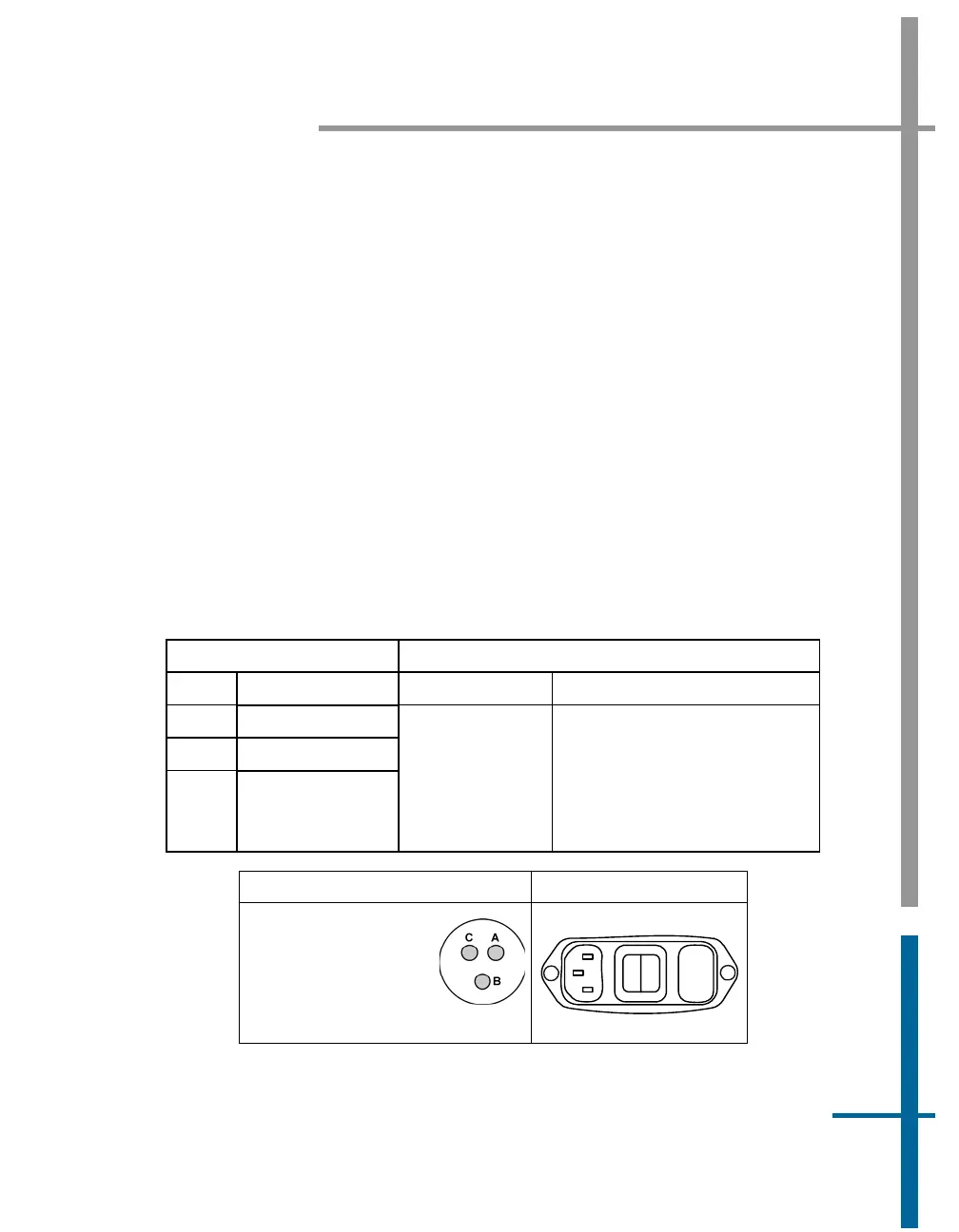
Power Interface
Power configuration is performed at Applanix prior to delivery. Table 4 and
Figure 8 identify the pin assignments.
Table 4: PWR Connector Pin Assignment
POS MV V4-1 POS MV V4
PIN Description Pin Description
A 24 Vdc at 2.5 A
B Return
C N/C
3-pin male
connector
accepts special
3-pin power
cable (see
Figure 89)
The internal power supply is
auto-switching between:
110 Vac at 1.0 A; 240 Vac at
0.25 A, 47 to 63 Hz
POS MV V4-1 POS MV V4
POS MV V4-1
Receptacle:
JD38999/24FA98PN
Cable Plug:
JD38999/26FA98SN
3 Pin
1
0
Fuse
Figure 8: PWR Connector Pin Arrangement