POS MV V4 User Guide
Installation
Copyright © Applanix Corporation, 2009
2-34
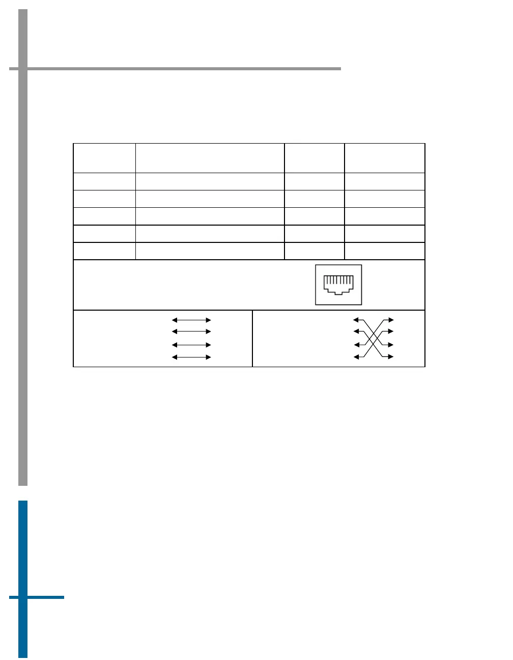
Table 11: Ethernet Connector Pin Assignment - POS MV V4
Pin Pin Description
Signal
Type
Signal
Direction
1 TX + Analog Bidirectional
2 TX - Analog Bidirectional
3 RX + Analog Bidirectional
6 RX - Analog Bidirectional
4, 5, 7, 8 N/C N/A N/A
POS MV Rear Panel
RJ-45 Female Connector
81
Pin out for a
straight
through
cable
TD+
TD-
TD+
TD-
RD+
RD+
RD-
RD-
3
2
1
6
3
2
1
6
Pin out for a
crossover
cable
TD+
TD-
RD+
RD-
TD-
TD+
RD+
RD-
3
2
1
6
3
2
1
6
The Ethernet interface provides a means for configuring and monitoring the
POS MV and conforms to the Institute of Electrical and Electronics Engineers
(IEEE) standard 802.3 that comprise the following types of ports:
• One control port - MV-POSView connects via TCP/IP and transmits
configuration information to the POS MV
• One display port - UDP provides data at a 1 Hz rate for use by MV-
POSView software
• Two data ports - One UDP and one TCP/IP provide the same data as
the Display port, at rates up to 200 Hz - (asynchronous events at
higher rates)