POS MV V4 User Guide
Installation
Copyright © Applanix Corporation, 2009
2-29
to the exact time when the event occurs. Connect the TTL signal to an event
in pin and it’s associated return pin.
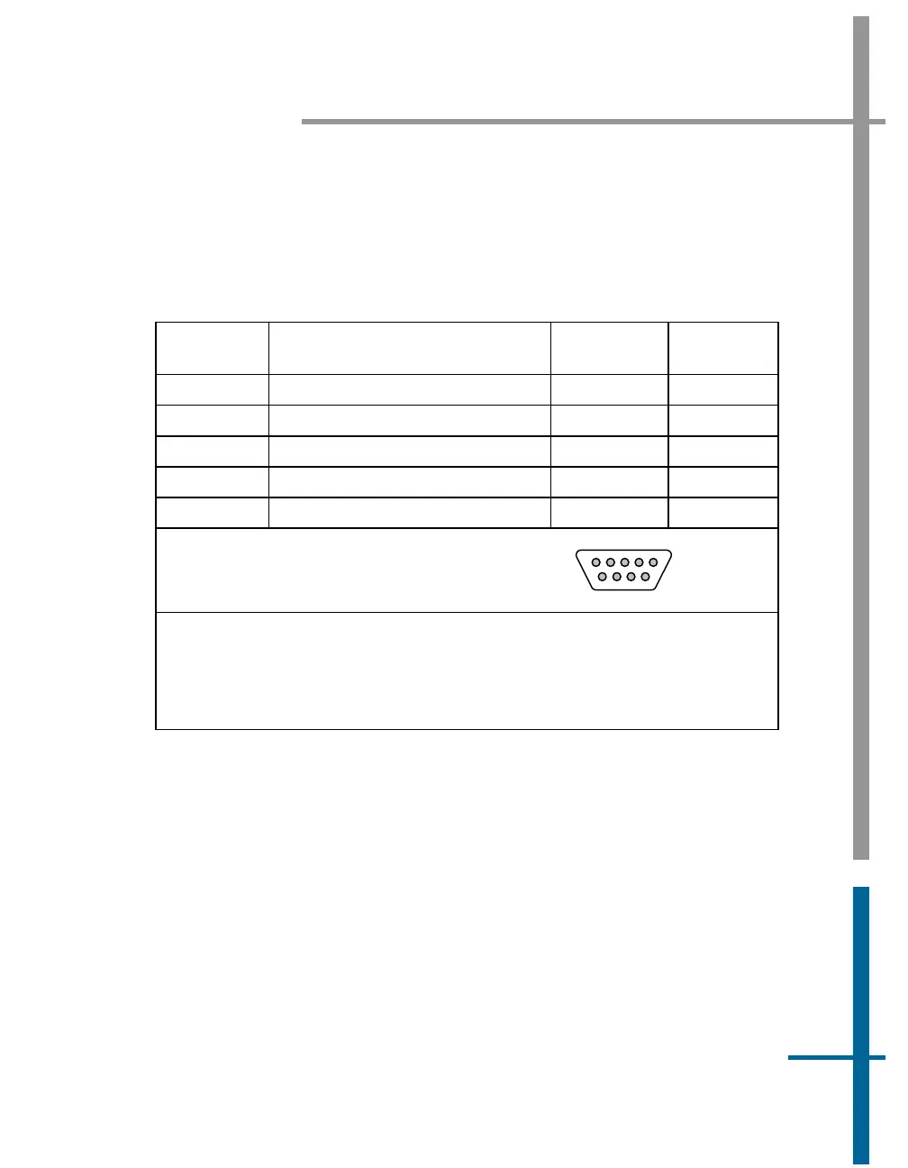
Table 10: EVENT Connector Pin Assignment
Pin Pin Description Signal Type
Signal
Direction
2 Event 1 In
* see notes * see notes
3 Event 2 In
* see notes * see notes
7 Event 1 Return
* see notes * see notes
8 Event 2 Return
* see notes * see notes
1, 4, 5, 6, 9 N/C N/A N/A
POS MV V4 Rear Panel
DB-9S Female Connector
1
5
69
* Event 1 In and Event 2 In are optically isolated digital inputs.
* Inputs (and their return lines) are un-referenced and are independent of internal
POS MV V4 and POS MV V4-1 power supplies and GND.
* Inputs can be controlled from an external 5V TTL-level source capable of
supplying a minimum of 5 - 10 mA of sourcing or sinking current.
Event Notes:
1. PCS Event 1 and Event 2 are optically isolated inputs and for proper
operation require a current flow of 5 - 10 mA between the “Input“ and
“Input Return” terminals.
2. Event 1 and Event 2 inputs can be driven by two types of the external
event generators:
• Type I event generator with an output capable of supplying
(sourcing) a current of 5 - 10 mA. For Event 1, the output
must be connected to the Isolated Event 1 (pin 2) with the