
D
David HodgeAug 16, 2025
What to do if the Applied Motion Products SV200 shows a position error?
- MMrs. Heather JonesAug 17, 2025
If the Applied Motion Products Controller experiences a position error, the suggested solution is to servo off.
What to do if the Applied Motion Products SV200 shows a position error?
If the Applied Motion Products Controller experiences a position error, the suggested solution is to servo off.
What should I do if my Applied Motion Products Controller has over current?
If the Applied Motion Products Controller is experiencing over current, the suggested solution is to servo off.
What happens if the Applied Motion Products Controller has a communication error?
If the Applied Motion Products Controller experiences a communication error, there will be no change to the drive’s status.
What to do when Applied Motion Products SV200 drive is over temperature?
If the Applied Motion Products Controller's drive is over temperature, the suggested solution is to servo off.
What should I do if the Applied Motion Products Controller shows a low voltage fault?
If the Applied Motion Products Controller experiences a low voltage fault, the suggested solution is to servo off.
What to do if STO is activated on Applied Motion Products SV200 Controller?
If the STO (Safe Torque Off) is activated on the Applied Motion Products Controller, the suggested solution is to servo off.
What happens when the Applied Motion Products Controller reaches the current limit?
If the Applied Motion Products Controller reaches its current limit, there will be no change to the drive’s status.
What happens when CW limit or CCW limit is activated on Applied Motion Products SV200 Controller?
If the CW (clockwise) or CCW (counter-clockwise) limit is activated on the Applied Motion Products Controller, there will be no change to the drive’s status.
What happens if regeneration failed in Applied Motion Products SV200?
If regeneration fails in the Applied Motion Products Controller, there will be no change to the drive’s status.
What happens if the Q program is empty on the Applied Motion Products SV200?
If the Q program is empty in the Applied Motion Products Controller, there will be no change to the drive’s status.
Covers essential safety information and precautions for operating the SV200 Servo Drive.
Explains the model naming convention and provides details on the SV200 series servo drives.
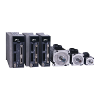
Introduces the SV200 servo motor series, covering model descriptions and specifications.
Illustrates the overall system configuration, showing connections between drives, motors, and peripherals.
Details environmental conditions and physical requirements for installing the servo drive and motor.
Provides guidelines for required ventilation and clearance when installing the servo drives.
Details the function and description of each connector and terminal on the SV200 servo drive.
Explains the wiring methods for the power supply connection (P1) for single and three-phase inputs.
Details the CN2 connector for input/output signals and its interface specifications.
Details the functions of the 12 configurable digital inputs and 2 analog inputs.
Explains the components and functions of the SV200 servo drive's control panel.
Explains how to select, view, and edit parameters using the control panel and software.
Lists essential safety checks and inspections before performing a trial run.
Provides a step-by-step procedure for conducting a trial run of the servo drive and motor.
Explains how to manually configure the motor settings using the drive's control panel.
Covers general settings for drive functions like servo ON/OFF and alarm reset.
Details the different types of position modes and their configuration.
Covers the configuration and operation of different velocity control modes.
Covers the configuration and operation of different torque control modes.
Provides a comprehensive list of all parameters, their SCL commands, LED display, and functions.
Offers detailed descriptions and explanations for various servo tuning and control parameters.
Explains RS-232 communication using port CN6 and the SCL command language.
Details the Modbus/RTU protocol, data encoding, addressing, and baud rates.
Covers Ethernet communication, including connecting a PC and setting IP addresses.
Explains the process of adjusting servo tuning gain parameters for optimal performance.
Guides on using the Auto-Tuning function to automatically optimize tuning parameters.
Covers manual fine-tuning of parameters to improve system performance after auto-tuning.
Details the implementation of Safe Torque Off (STO) function and its safety specifications.
Outlines requirements for testing safety functions, including inspection and parameter verification.
Lists all drive alarms, their descriptions, alarm types, and drive status after occurrence.
Provides processing methods for troubleshooting common drive alarms and fault conditions.
Provides a reference for characters displayed on the LED segment display.
Lists accessories and mating connectors required for the SV200 series.
| Brand | Applied Motion Products |
|---|---|
| Model | SV200 |
| Category | Controller |
| Language | English |