HVAC EQUIPMENT
RETURN
SUPPLY
SUPPLY
HVAC EQUIPMENT
RETURN
SUPPLY
HVAC EQUIPMENT
RETURN
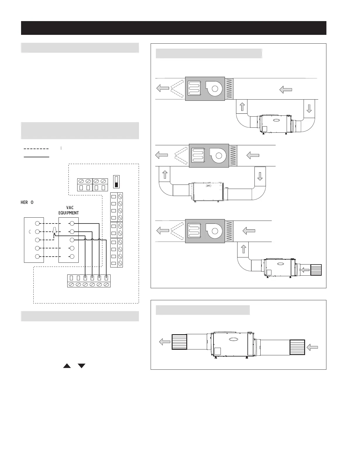
MAIN RETURN TO MAIN SUPPLY
MAIN RETURN TO MAIN RETURN – RECOMMENDED
DEDICATED RETURN TO MAIN SUPPLY OR RETURN
DEDICATED RETURN TO DEDICATED SUPPLY
SHEET 1 – SINGLE ZONE USING INTERNAL CONTROL
PARTS NEEDED (ADDITIONAL PARTS MAY BE REQUIRED)
• Model E080/E100/E130
• Insulated duct
• Duct fittings & hardware
• Grilles (if required)
• Drain pan and float switch (if required)
• Thermostat wire
• 20A outlet (E130 only)
WIRING INTERNAL CONTROL (SHOWN WITHOUT
“DISABLE WITH AC” FEATURE BEING USED)
FIGURE 1 – DEHUMIDIFIER DUCTED TO HVAC SYSTEM
FIGURE 2 – DEHUMIDIFIER DUCTED DIRECTLY
SEQUENCE OF OPERATION
The dehumidifier will automatically “sample” the air by
turning on its blower (and the HVAC blower if this option
has been wired – see WIRING INTERNAL CONTROL
above), and measuring the relative humidity (RH) once
every hour. Sampling will also occur when the RH setting
is lowered using the
or buttons on the control.
During sampling, if the RH of the air is above the
setting the dehumidifier, the compressor will turn on.
The compressor, dehumidifier blower and HVAC system
blower (if on) turns off when the RH of the air is 3% RH
below the setting.
H
Q
M
NT
ZONE CONTROL
BOARD
R
G
W
Y
NEW WIRE
ODT
SENSOR
DH DH
REMOTE
+ - A B
HVAC EQUIP
Gh Rf Cf Gs W Y
DAMPERS
VENT DEH
FLOAT
SWITCH
DEHUMIDIFIER
CONTROL
BOARD
NC
NO
R
C
G
W
Y
WIRING TO THE HVAC
SYSTEM IS REQUIRED
IF DUCTING RETURN
TO RETURN, OPTIONAL
FOR ALL OTHER
INSTALLATIONS.
2
 Loading...