YC500A/I Installation/User Manual
YC500I Installation Procedures
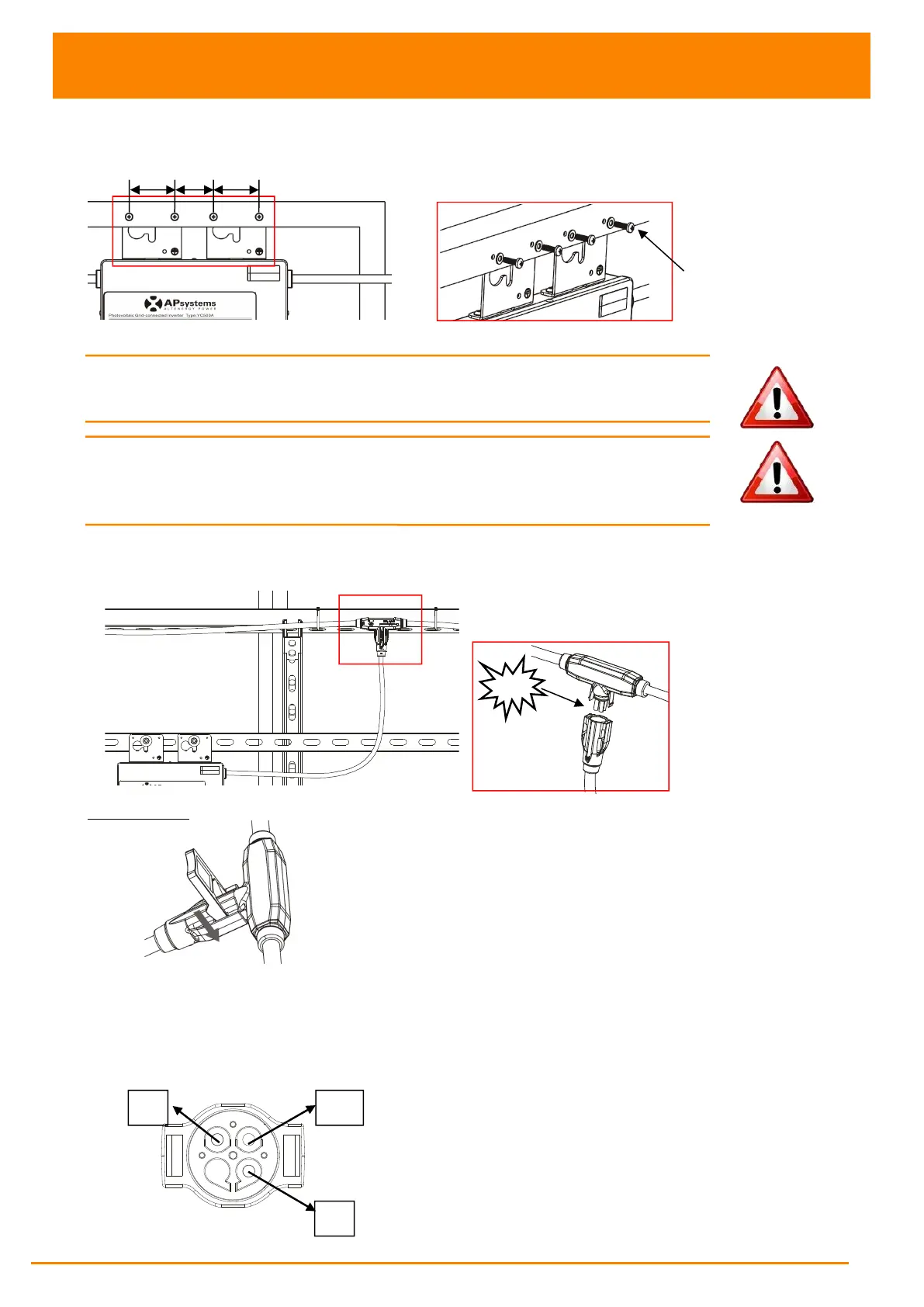
Attach to the PV module frame.
Drill holes on the PV module frame before installing YC500I. Please check with
the module manufacturer the compatibilty of such installation process.
Figure 19
WARNING: Prior to installing any of the microinverters, verify
that the utility voltage at the point of common connection matches
the voltage rating on microinverter label.
WARNING: Do not place the inverters (including DC and AC connectors)
Where exposed to the sun, rain or snow, even gap between modules.
Allow a minimum of 3/4’’(1.5cm.) between the roof and the bottom of the
Microinverter to allow proper air flow.
Stpe 4 - Connect the APsystems microinverter to AC bus cable
Figure 20
Best Practice: Use the Bus Cable Unlock Tool of AC Bus to split the connectors.
a. Check the Microinverter
technical data page(p.22)
for the maximum
allowable number of Microinverters on each AC branch circuit.
b. Plug the AC connector of the Microinverter into the AC bus
AC connector interface as follows.
Figure 21