YC500A/I Installation/User Manual
YC500I Installation Procedures
Cover any unused connectors with Bus Cable T-CONN Cap to protect the connectors.
Figure 22
WARNING: Do NOT exceed maximum number of Microinverters
in an AC branch circuit, as displayed on the Technical Data page
(p.22) of this manual.
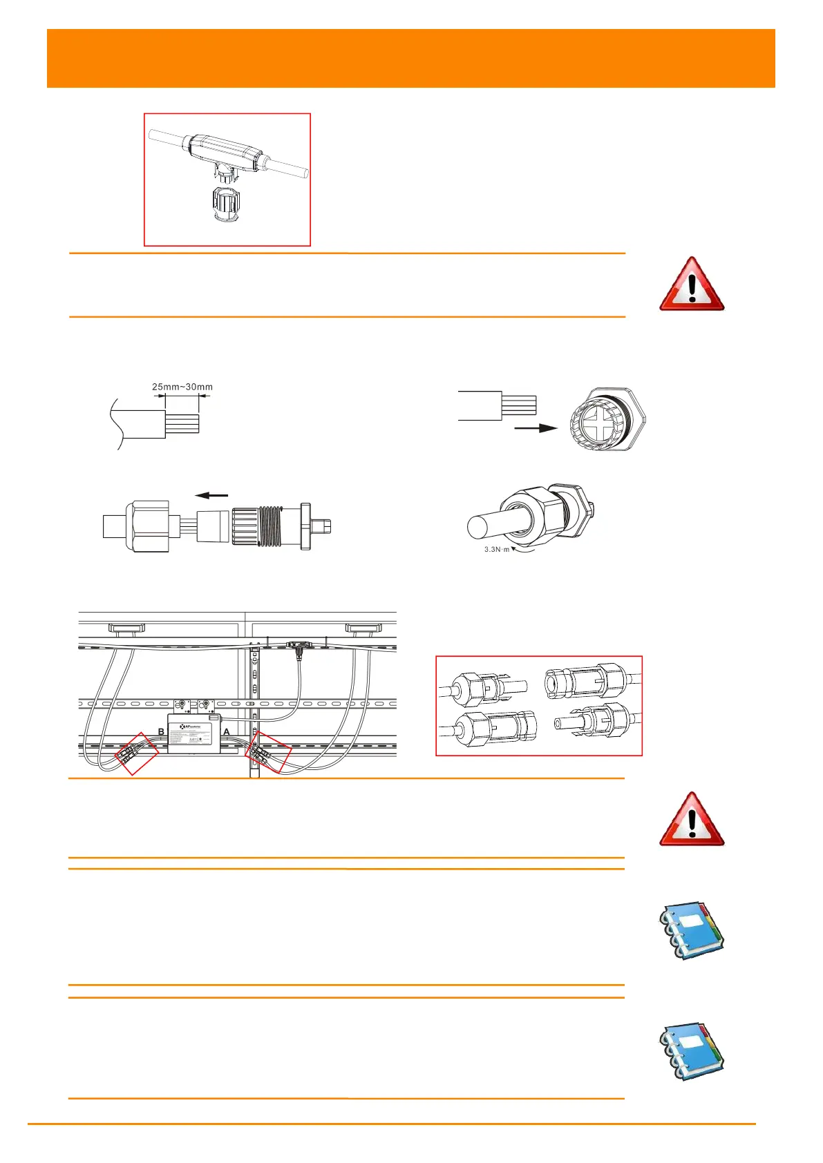
Step 5 - Install a Bus Cable End Cap at the end of AC bus cable
a. Strip cable jacket. c. Insert the wires into the cable clamps.
b. Insert the cable end into the seal. d. Rotate the nut with 3.3N·m until the
latching mechanism meets the base.
Figure 23
Step 6 - Connect APsystems Microinverters to the PV Modules
Figure 24
WARNING:
Double check to make sure all of the AC and DC wiring
has been correctly installed. Ensure that none of the AC and/or DC
wires are pinched or damaged. Make sure that all of the junction
boxes are properly closed.
NOTE: When plugging in the DC cables, the Microinverter should
immediately blink one quick red and three short green. This will happen
as soon as the cables are plugged in and will show that the Microinverter is
functioning correctly. This entire check function will start and end
within 5 seconds of plugging in the unit, so pay careful attention to
these lights when connecting the DC cables.
NOTE: About A and B Sides corresponding the location of modules,
EMA registration show acquiesce in this installation. if there are
different connection methods, please email the detail installation
drawings to us to register, or the A, B Sides corresponding component
location will not correspond to the EMA position.