YC500A/I Installation/User Manual
YC500I Installation Procedures
Step 1 - Position the AC bus cable
Step 2 - Install the AC branch circuit junction box
Figure 16
a. Install an appropriate junction box at a suitable location on the PV racking system
((typically at the end of a branch of modules).
b. Connect the open wire end of the AC bus cable into the junction box using an appropriate
gland or strain relief fitting.
c. Wire the conductors of the AC bus: L - BROWN; N - BLUE; PE - YELLOW GREEN.
d.
Connect the AC branch circuit junction box to the point of utility interconnection.
WARNING:
Wiring colour code can be different according local regulation,
check all the wires of the installation before connecting to the AC bus to be
sure they match.Wrong cabling can damage irreparably the microinverters,
such an issue is not covered by the warranty.
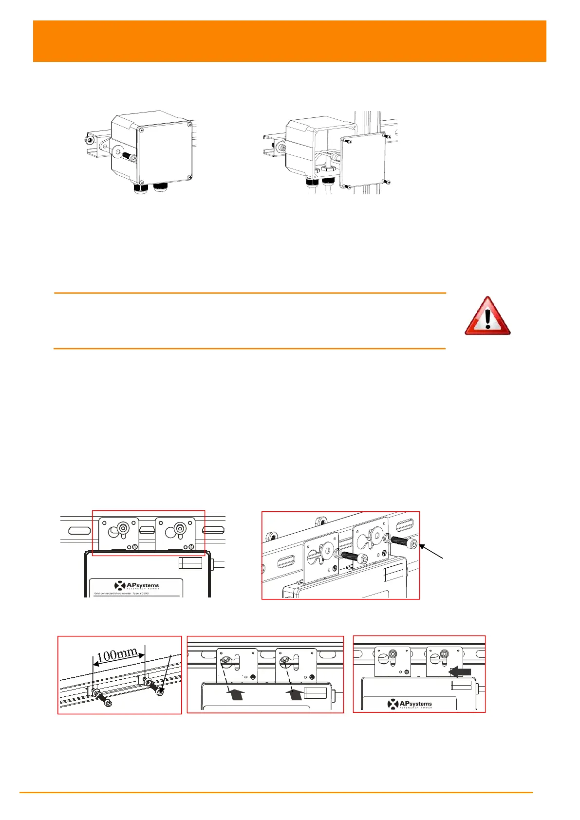
Step 3 - Attach the APsystems Microinverters to the racking or
the PV module frame
Attach to the racking
a. Mark the location of the Microinverter on the rack, with respect to the PV module
junction box or any other obstructions.
b. Mount one Microinverter at each of these locations using hardware recommended by
your module racking vendor.
Option 1:
Figure 17
Option 2:
Figure 18
M8
(not supplied by APsystems)