C.8 Option 10: Inlet Power Supply Description 107
C.8 Option 10: Inlet Power Supply Description
C.8.1 110 to 350 VDC, 85 to 250 VAC, 47 to 440 Hz Terminal Power Strip,
SWC
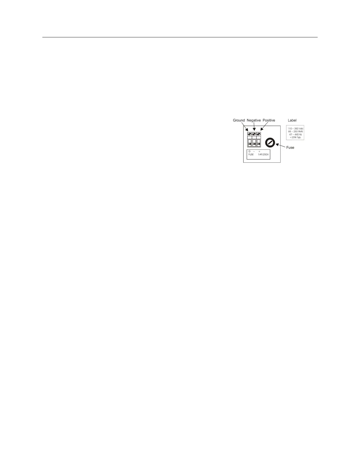
Option 10 replaces the standard IEC-320 power input module with a three-position, screw-type
terminal block, including Surge Withstand Capability (SWC). This feature is intended for use
in installations where it is necessary or desirable to have the instrument power hard-wired. See
Figure C.6.
Figure C.6: Option 10 Power Supply Inlet
Description
C.8.2 Specifications
Input Power:
AC Voltage Range: 85 to 250 VAC
Frequency Range: 47 to 440 Hz
DC Voltage Range: 110 to 350 VDC
Input Power: < 20 Watts
Terminal Block:
Terminal Assignment:* Ground, (−), (+), left to right, viewed from rear
Block Size: 15 mm W x 18 mm H x 30 mm D. (5/8” x 0.75” x 1 3/16”)
Approvals: U. L. recognized; C.S.A. approved
*For AC operation, input line may be connected between (+) and (−), without
regard to polarity; however proper grounding should always be employed
Fuse:
Type: Bussman GDC-1A
Current Rating: 1 Ampere, fast-acting
Voltage Rating: 250 Volts
Size: 5 mm x 20 mm
Surge Withstand Protection (SWC)
Provides input Surge Withstand Capability (SWC) in compliance with both ANSI C37.90 and IEC
801-4.
Connections
All input power line connections to the rear-panel terminal strip should be made using appropriate
power cables which have the insulation removed about 1/4” from the end or as required for tinning.
If a DC source is used, connect the positive lead to the positive (+) terminal, connect the negative
lead to the negative (−) terminal and a safety ground lead to the “G” terminal when viewing the
instrument from the rear (see Figure C.6).