Do you have a question about the Arbiter Systems 1092A and is the answer not in the manual?
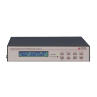
Details on front panel LEDs, display, and keypad functions.
Identification of rear panel connectors for power, antenna, and communication.
Instructions for connecting output signals to designated connectors.
Instructions for connecting input signals via terminals and connectors.
Guidance on mounting the GPS antenna for optimal signal reception.
Identifies jumper and test point locations on the main board.
Describes the sequence of events and LED indications upon powering on.
Explains the LCD display indications during startup and other states.
Guide to configuring the clock using setup menus or RS-232.
Configuration steps for the main RS-232 port parameters and broadcast mode.
Setting local time offset and Daylight Saving Time configurations.
Configures how the clock responds to out-of-lock conditions.
Configures various programmable pulse modes and parameters.
Adjusts IRIG-B time data for Local time and IEEE-1344 extension.
Configures modes for event timing or 1 PPS deviation measurement.
Controls how the clock determines position information via Auto Survey.
Enables or disables the Position Hold timing mode.
Describes the rear panel connectors for timing outputs.
Details the different digital and analog timing signals available.
Instructions for connecting outputs using screw terminals and adapters.
Configuration for event timing input with microsecond resolution.
Information for controlling and communicating with clocks via RS-232.
Describes I/O connectors, signal types, and configurable outputs.
Specifications for clock power requirements and options.
Description of the power system monitoring option.
Setup and configuration for NTP/PTP server option.
| Category | Measuring Instruments |
|---|---|
| GPS Receiver | Yes |
| Inputs | 3 voltage, 3 current |
| Display | LCD |
| Interfaces | RS-232, RS-485, Ethernet |
| Power Supply | 85 to 264 Vac, 47 to 63 Hz |
| Frequency Range | 45 to 65 Hz |
| Outputs | RS-232, RS-485 |
| Dimensions | 19" rack mount, 1U height |