E-16
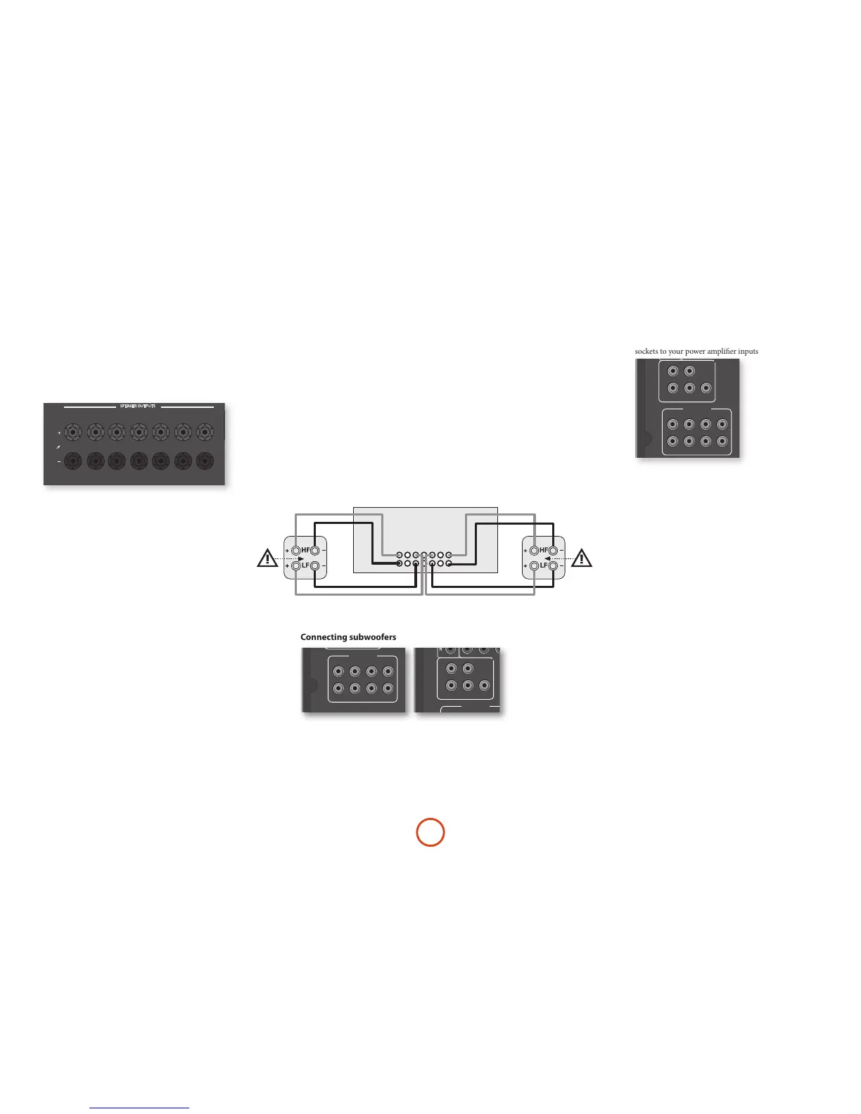
Connecting speakers
To connect each of the speakers, unscrew the
corresponding terminals on the back of the Receiver,
insert the speaker wires through the hole in each post
and screw the terminals back up. Make sure that the
red (positive/+) terminal of the speaker is connected to
the red (positive/+) terminal on the back panel, and the
black (negative/–) terminal of the speaker is connected
to the black (negative/–) terminal on the back panel.
It is important that no stray strands of wire from these
connections are allowed to touch another cable or the
product casing. Failure to ensure this can cause a short
circuit and damage your Receiver.
Do not over-tighten the loudspeaker terminals, or use a
wrench, pliers, etc., as this could damage the terminals
and this would not be covered under the product’s
warranty.
Speaker cables
e speakers should be connected to the amplier using
good-quality, high-purity, low impedance copper cables.
Cheap speaker cables should be avoided – they are a
false economy and can signicantly degrade the sound
quality.
e cable runs to the speakers should be as short as
practicable. Connections to the speaker terminals
should always be nger tight, whether using bare wires
or spade connectors.
FL
FR
SBR
SBL
Link MUST
be removed
Link MUST
be removed
Bi-amping the Front Left & Front Right speakers
Bi-amping is the use of two amplier channels per speaker. Bi-amping can
provide better sound quality than conventional single wiring. If you do not have
Surround Back speakers (i.e. you have a 5.1 surround system, not a 7.1 system)
then you can use the spare Surround Back speaker outputs to bi-amplify the
front le and right speakers, if your speakers support bi-amping. e spare
channels can alternatively be used to power stereo speakers in another room
(Zone 2).
Speakers that support bi-amping have two sets of +/- terminals per speaker,
usually linked together by metal strips. ese metal strips MUST be removed
when bi-amping; failure to remove them will result in damage to the amplier
that is not covered under warranty.
To bi-amp the front le and right speakers, remove the metal strips from
the speaker terminals. Connect the woofer or LF terminals to the FL and FR
terminals on the Receiver. Connect the tweeter or HF terminals to the SBL and
SBR terminals on the Receiver. Finally, navigate to the Setup Menu ‘Spkr Types’
and set the ‘Use Channels 6+7 for’ menu option to ‘BiAmp L+R’; see page E-26.
Using external power amplifiers
e internal power amplier of the Receiver (SR250
L, R, Sub only) can be supplemented or replaced with
external power amplication, such as the Arcam P49
(recommended gain 31dB). Connect the PREAMP OUT
sockets to your power amplier inputs:
PREAMP OUT
FL, FR
Connect these to the equivalent Right and Le front
channels of your power amplier. For the SR250, only
this and the sub outputs are available
C
Connect these to the Centre front channel of your
power amplier.
SUB
Subwoofer outputs. Connect this to the input of your
active subwoofer(s), if present. For the SR250, only this
and the FL, FLR outputs are available
SR, SL
Surround Right and Surround Le outputs. Connect
these to the Surround Right and Le power amplier
inputs.
SBR, SBL
Surround Back Right and Surround Back Le outputs
(only used in 7.1 channel systems). Connect these to the
Surround Back Right and Surround Back Le power
amplier inputs.
Height 1, Height 2
Height 1 and Height 2. Connect these to the Height 1
and/or Height 2 power amplier inputs.
All preamplier analogue outputs are buered, have
a low output impedance and are at line level. ey are
able to drive long cables or several inputs in parallel if
required.
Connecting subwoofers
 Loading...