Item Feature Item Feature
J4
Screw terminal block for power supply and
CAN bus interface
J5 Battery socket
J8 Mini PCIe connector J10
MIPI camera connector (only compatible with
Portenta X8 boards)
J11 DVP interface connector J12 microSD card slot
J13
USB-A 2.0 female connector for data logging
operations
J14,
J15
2.54 mm breakout header connectors
J16 Mini PCIe breakout header connector J17 2.54 mm breakout header connectors
J18 RJ45 connector for Ethernet J19 GIGA Display Shield Connector
SIM1 Nano SIM card connector SW1 Boot select switch
SW2 CAN bus interface enable/disable switch SW3 Ethernet enable/disable switch
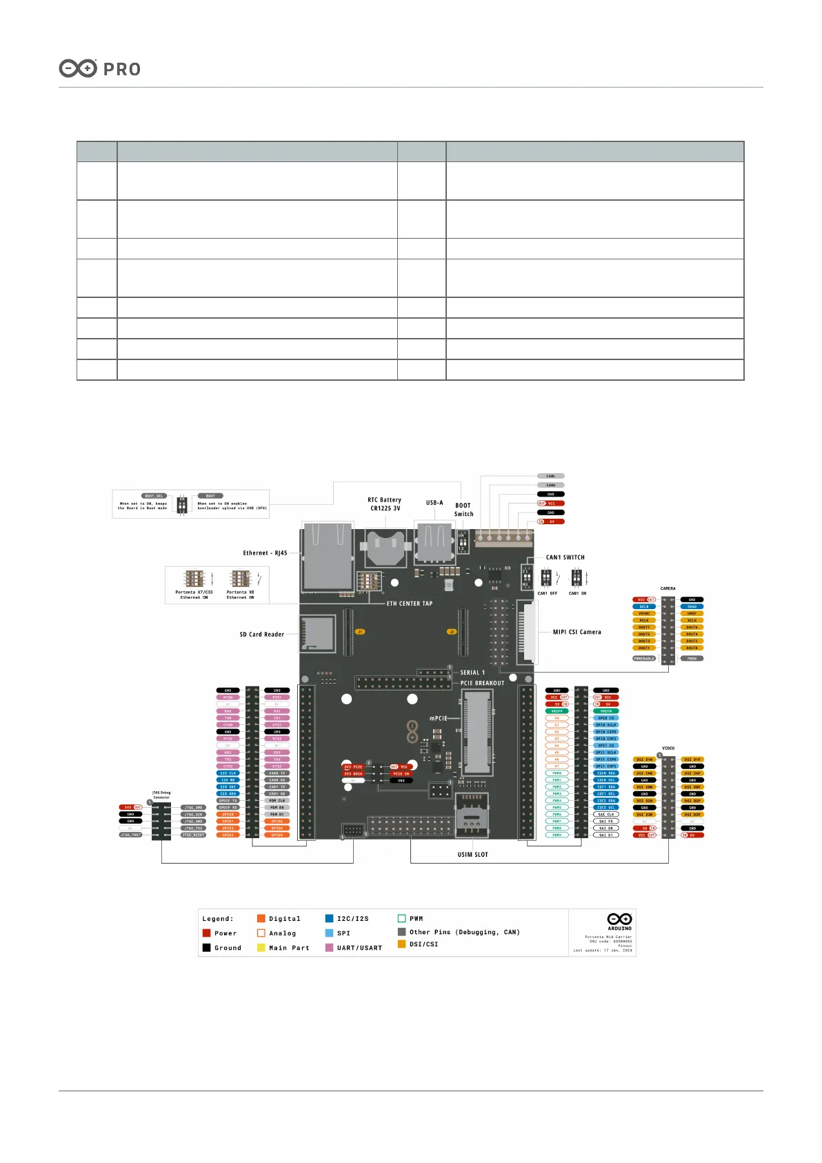
4.2 Simple Pinout
The Portenta Mid Carrier simple pinout is shown in the figure below.
 Loading...


