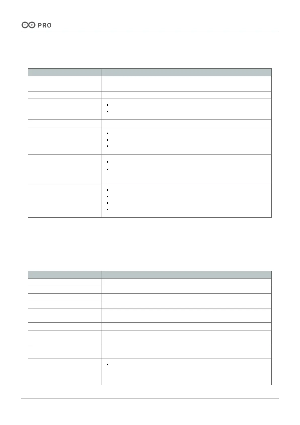
2.2 Communication Interfaces
Interfaces Connector
Mini PCIe (x1) Mini PCIe connector (J8), High-Density connectors (J1-J2) and breakout header
connector
1
(J16)
Ethernet (x1) RJ45 connector (J18)
SPI (x2)
SPI0: Breakout header connector (J15) and High-Density connector (J2)
SPI1: Breakout header connector (J15) and High-Density connector (J2)
I2S (x1) Breakout header connector (J14) and High-Density connector (J1)
I2C (x3)
I2C0: Breakout header connector (J15) and High-Density connector (J1)
I2C1: Breakout header connector (J15) and High-Density connector (J1)
I2C2: Breakout header connector (J15) and High-Density connector (J2)
CAN bus (x2)
CAN0
2
: Breakout header connector (J14) and High-Density connector (J1)
CAN1
3
: Breakout header connector (J14), High-Density connector (J1), and
screw terminal block (J4)
UART (with flow control) (x4)
SERIAL0: Breakout header connector (J14) and High-Density connector (J1)
SERIAL1: Breakout header connector (J14) and High-Density connector (J1)
SERIAL2: Breakout header connector (J14) and High-Density connector (J2)
SERIAL3: Breakout header connector (J14) and High-Density connector (J2)
1
For debugging purposes only.
2
CAN0 has no CAN PHY; an external one is needed.
3
CAN1 has an onboard CAN PHY available through the Carrier's screw terminal block (J4); it can be enabled or
disabled via a DIP switch (SW2).
2.3 Other Features
Feature Description
Additional onboard storage microSD card slot (J12) for data logging operations
SIM card support Yes, available through the Carrier's Mini PCIe interface
RTC Support Yes, available through the Carrier's onboard CR1225 battery socket
USB support USB-A 2.0 female connector (J13) for data logging operations
Camera support
Yes, through the MIPI camera connector (J10) and the DVP interface connector
(J11)
Display support Yes, available through the Carrier's GIGA Display Shield connector (J19) (x1)
Video support
Only with the Portenta H7 and the Portenta X8 boards through its onboard
USB-C® connector
Camera support
4
Yes, available through the MIPI camera connector (J10) and the DVP interface
connector (J11)
DIP switches
ETH CENTER TAP (SW3): All positions OFF to enable Ethernet for the
Portenta X8 board; for the Portenta C33 and H7 boards, Ethernet is always
enabled regardless of the switch positions
 Loading...


