User Manual – Arenal PCS – QA03-SDA Page 16/74
3.4 Internal wiring
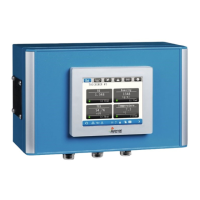
The power AC/DC convertor is situated on the left side of the main board. In case of DC supply voltage, this
module is replaced by a DC/DC convertor. The fuses are just on the top‐right of it. The 24Vdc power output
of the power convertor is connected through the main board to the power supply of the HMI and the IO
Module. Also external transmitters are powered by this 24Vdc.
After opening the lid, the baseboard is visible.
On the left side, the power convertor is placed.
The IO module will be place in the middle.
The UDT is connected to the Modbus connector, see drawings in enclosures.
The RMM is connected to the PoE Ethernet adapter.
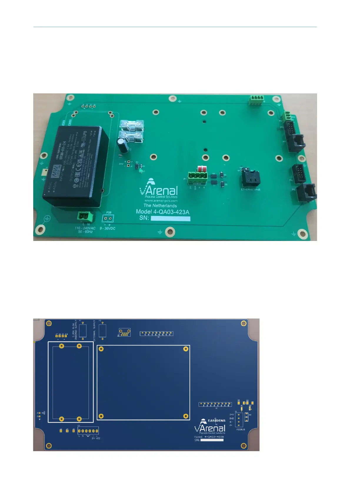
Below the special mainboard for customers in South Africa, supplied by our partner KRT Instruments.
 Loading...