NOTE
HT : Using the booster cable
H:
At shipment
20
Air Flow (m
3
/minute)
External Static Pressure
0
50
0
5
10
15150
10
Limit line
Limit line
HT
H
L
100
M
(mmAq)
(Pa)
30 40
Air Flow (m
3
/minute)
External Static Pressure
0
50
0
5
10
15
150
20
Limit line
Limit line
L
100
M
H
(mmAq)
(Pa)
HT
30
Air Flow (m
3
/minute)
External Static Pressure
0
50
0
5
10
15
150
20
Limit line
HT
L
100
M
H
Limit line
(mmAq)
(Pa)
ADS125PHADS100PHADS71PH
Indoor Fan Performance
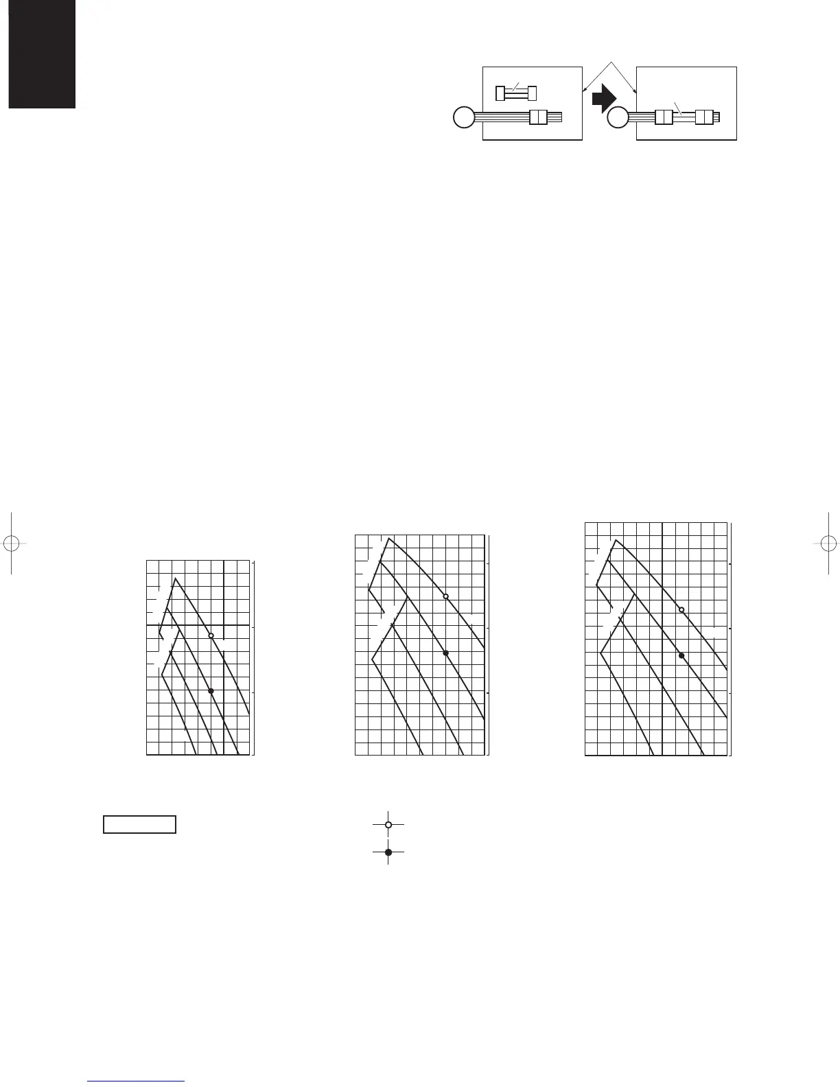
1-9. Indoor Fan Performance
Concealed-Duct Type
If external static pressure is too great (due to long
extension of ducts, for example), the air flow volume
may drop too low at each air outlet. This problem may
be solved by increasing the fan speed using the fol-
lowing procedure:
(1) Remove 4 screws on the electrical component box
and remove the cover plate.
(2) Disconnect the fan motor sockets in the box.
(3) Take out the booster cable (sockets at both ends)
clamped in the box.
(4) Securely connect the booster cable sockets
between the disconnected fan motor sockets in
step 2 as shown in Fig. 1-1.
(5) Place the cable neatly in the box and reinstall the
cover plate.
Fig. 1-1
Fig. 1-2
Booster cable
Booster cable
Electrical component box
(At shipment) (Booster cable installed)
Fan motor socket
Fan
motor
■ How to read the diagram
The vertical axis is the external static pressure (Pa) while the horizontal axis represents the air flow (m
3
/minute). The
characteristic curves for “HT,” “H,” “M” and “L” fan speed control are shown. The nameplate values are shown based
on the “H” air flow. For the 25 type, the air flow is 18 m
3
/minute, while the external static pressure is 49 Pa at “H”
position. If external static pressure is too great (due to long extension of ducts, for example), the air flow volume may
drop too low at each air outlet. This problem may be solved by increasing the fan speed as explained above.
04-309 Sanyo-1_p96-127 10/27/04 2:07 PM Page 114