4
4 - 14
Check Pin
Short-circuit the cooling check pin (or heating check pin) on the outdoor unit control PCB to perform the control
described below.
1. Thermistor checks
The checks listed below are performed for 1 second each, in order from the top down. The results are dis-
played by LED 1 and 2.
↓
2. 4-way valve turns ON for 1 second.
↓
3. Forced cooling (or heating) operation
Discharge temp. (TD)
Outdoor air temp. (TO)
Heat exchanger temp. (C1)
Heat exchanger temp. (C2)
Intake temp. (TS)
Thermistor
Check results
Normal Abnormal
LED 1 and 2 OFF
LED 1 lit
LED 1 lit
LED 1 lit
LED 2 lit
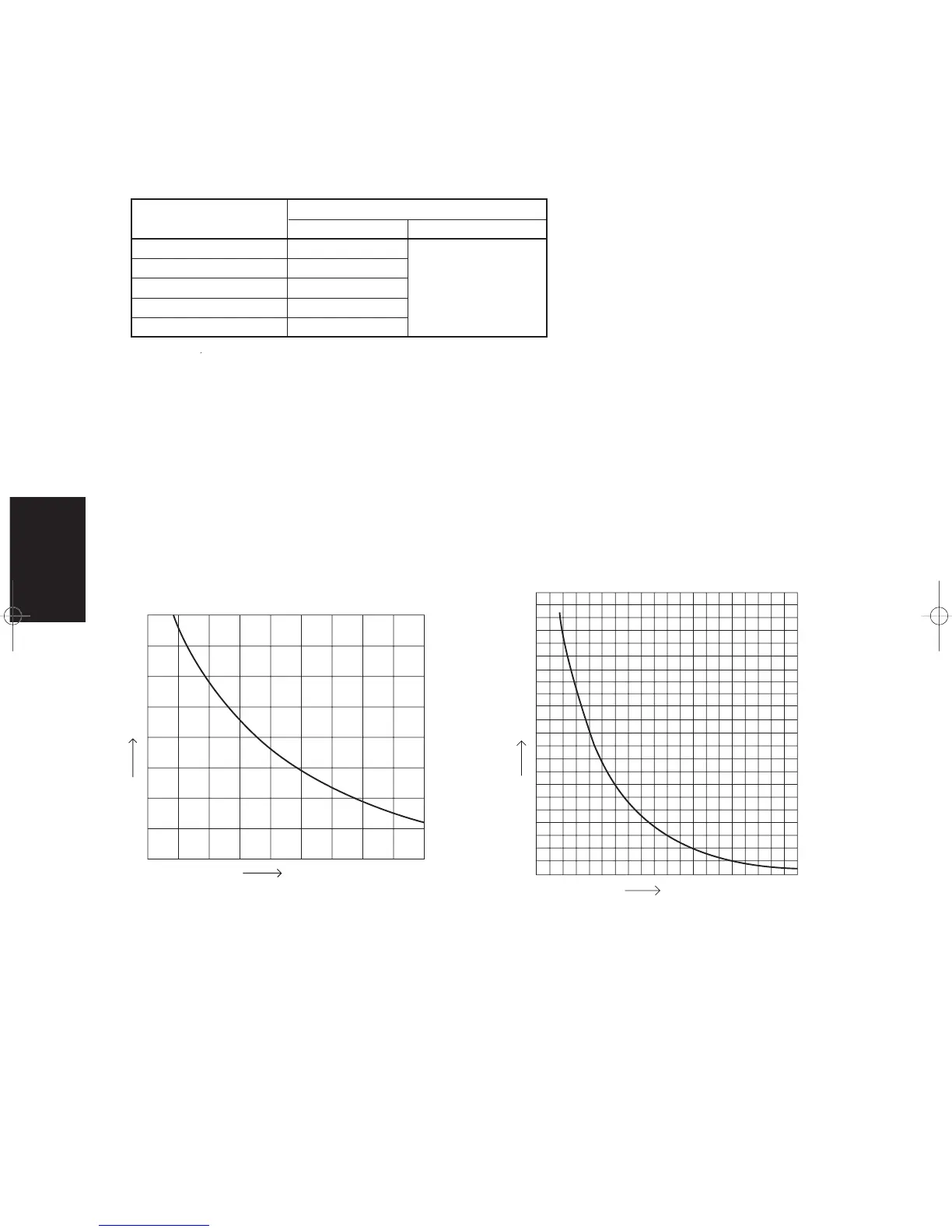
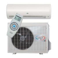
4-5. Table of Thermistor Characteristics
(1) Outdoor Air Temp. (TO), Intake Temp. (TS),
Heat Exchanger Temp. (C1) Sensor, Heat
Exchanger Temp. (C2) Sensor
(2) Discharge Temp. (TD) Sensors
Temperature (°C)
Resistance (kΩ)
Temperature (°C)
Resistance (kΩ)
04-309 Sanyo-4 10/27/04 1:48 PM Page 14