38
NOTE:Useapairofmodied7RViceGripstoholdtheends
of the chain together while inserting the connecting link. There
may be no slack in the idler chain, making installation of the
connectinglinkdicultwithoutthistool.ModiedViceGrips
can be ordered from your ARGO dealer (ARGO Part No.
658-08)orrefertoAppendix1formodicationinformation.
3. Install the outside plate and secure with the cotter pins.
Note: Always use new cotter pins. Figure 7-18a.
4. Repeat steps 1 to 3 to replace the other idler chain.
Figure 7-18a. Chain link cotter pins (idler chains)
7.2.6 TIRE INFLATION
Improperlyinatedtirescancausethevehicletopulltoone
side,requiringconstantsteeringcorrection.Suggestedina-
tion is based on the type of rim in the wheel, and are listed
below.
Standard 8" Steel Rim 2.5 to 3.5 psi
(17 to 24 kPa)
Standard 9" Steel Rim 2.5 to 3.5 psi
(17 to 24 kPa)
Oset9"SteelRim 2.5to3.5psi
(17 to 24 kPa)
Oset9"AluminumBeadlock Rim 1.5 to 3.5 psi
(10 to 24 kPa)
The maximum operating pressure for all tires is 7.0 psi (48
kPa).
A special low pressure tire gauge (ARGO Part No. 619-10) is
available from your ARGO dealer.
CHANGING TIRE PRESSURE FOR DIFFERENT
TERRAIN CONDITIONS
Thetirepressureshouldbeadjustedaccordingtodierencesin
terrain. Observance of these guidelines will lead to less wear
& tear on both vehicle and tires. The operator should equip
the vehicle with a low pressure tire gauge (Part No. 619-10)
and with a hand pump.
SECTION 7
MAINTENANCE INFORMATION
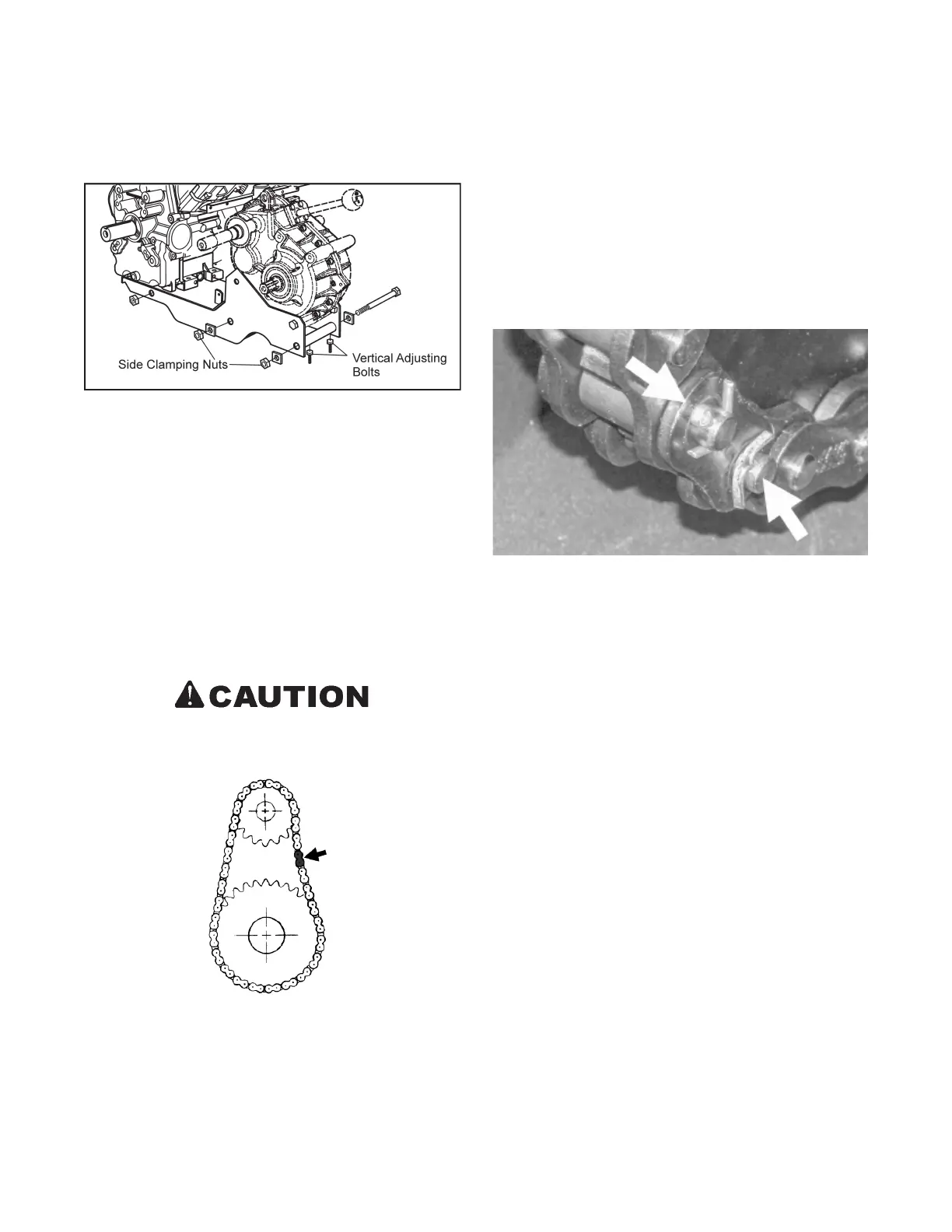
4. Tighten the 2 left side clamping nuts securely. Torque to
80ft./lbs.
Figure 7-17. Location of power pack clamping nuts
and adjusting bolts
To Remove the Idler Chains:
Loosen the power pack clamping nuts and adjusting bolts as
shown in Figure 7-17 and proceed as follows:
1. Place the gearshift in neutral and roll the vehicle until the
connecting link of one of the idler chains is positioned as
shown in Figure 7-18.
2. Remove the cotter pins from the connecting link. Remove
the outside plate and tap out the connecting link.
3. Remove the idler chain from the vehicle.
4. Repeat steps 1 to 3 to remove the other idler chain.
Do not over tighten idler chains. Premature chain
wear, bearing wear or idler shaft failure can occur.
Figure 7-18. Position of idler chain link for removal.
To Install the Idler Chains:
1. Install the chain over the brake disc sprocket and the idler
shaft sprocket.
2. Pull the ends of the chains together and insert the connect-
ing link.