60 /
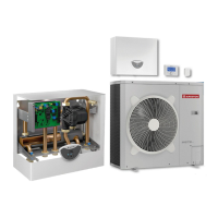
Overall view
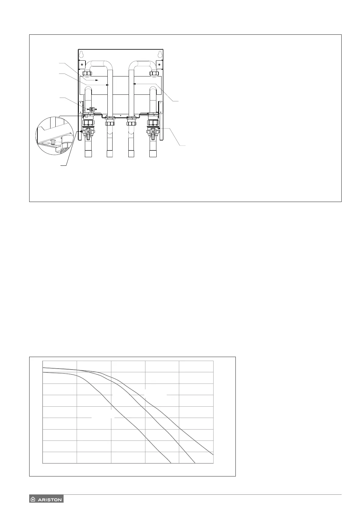
Available pressure
The curves indicated above show the available pressure of internal units.
In order to have a correct sizing of the system, the pressure drop curve of the entire circuit (in function of the nominal fl ow
rate) must stay below the available pressure curve everywhere. Pressure drop values depend on the specifi c installation.
You can install a supplementary circulation pump if the module’s own unit is not powerful enough. For the electrical
hookup, refer to "Electrical circuit".
Warning: in case of installation of thermostatic valves on all terminals or zone valves, install a bypass to ensure the mini-
mum operating fl ow rate.
WARNING:
the heating system must be fully deaerated by performing the deaeration cycle as described in the ignition procedure,
and by opening the air relief valves located on the system.
1. Heat generator delivery pipe
2. Heat generator return pipe
3. Inlet valve for hot water from external
unit G 1" M
4. Heating system delivery valve
G 1" M
5. Water mains tap
6. Heating system delivery temperature
sensor
7. Manifold
0
1
2
3
4
5
6
7
8
9
0 500 1000 1500 2000 2500
[l/h]
[mce]
70
90-110
40-50
AVAILABLE PRESSURE
5
1
7
3
2
4
6
 Loading...