62 /
REMOTE CONTROL DEVICE TECHNICAL DATA
Power supply BUS
Electrical absorption max. < 0.5W
Operating temperature -10 to 60°C
Storage temperature -20 to 70°C
Bus wire length and cross-sectional area
NOTE: IN ORDER TO AVOID INTERFER
ENCE PROBLEMS, USE
A SHIELDED CA
BLE OR TWISTED PAIR CABLE.
max. 50 m
min. 0.5 mm²
Bu er memory 2 h
Conformity
LVD 2006/95/EC - EMC 2004/108/EC
Electromagnetic interference EN 60730-1
Electromagnetic emissions EN 60730-1
Conformity to standards EN 60730-1
Temperature sensor NTC 5 k 1%
Resolution degree 0.1°C
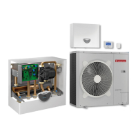
134 mm 16 mm
96 mm
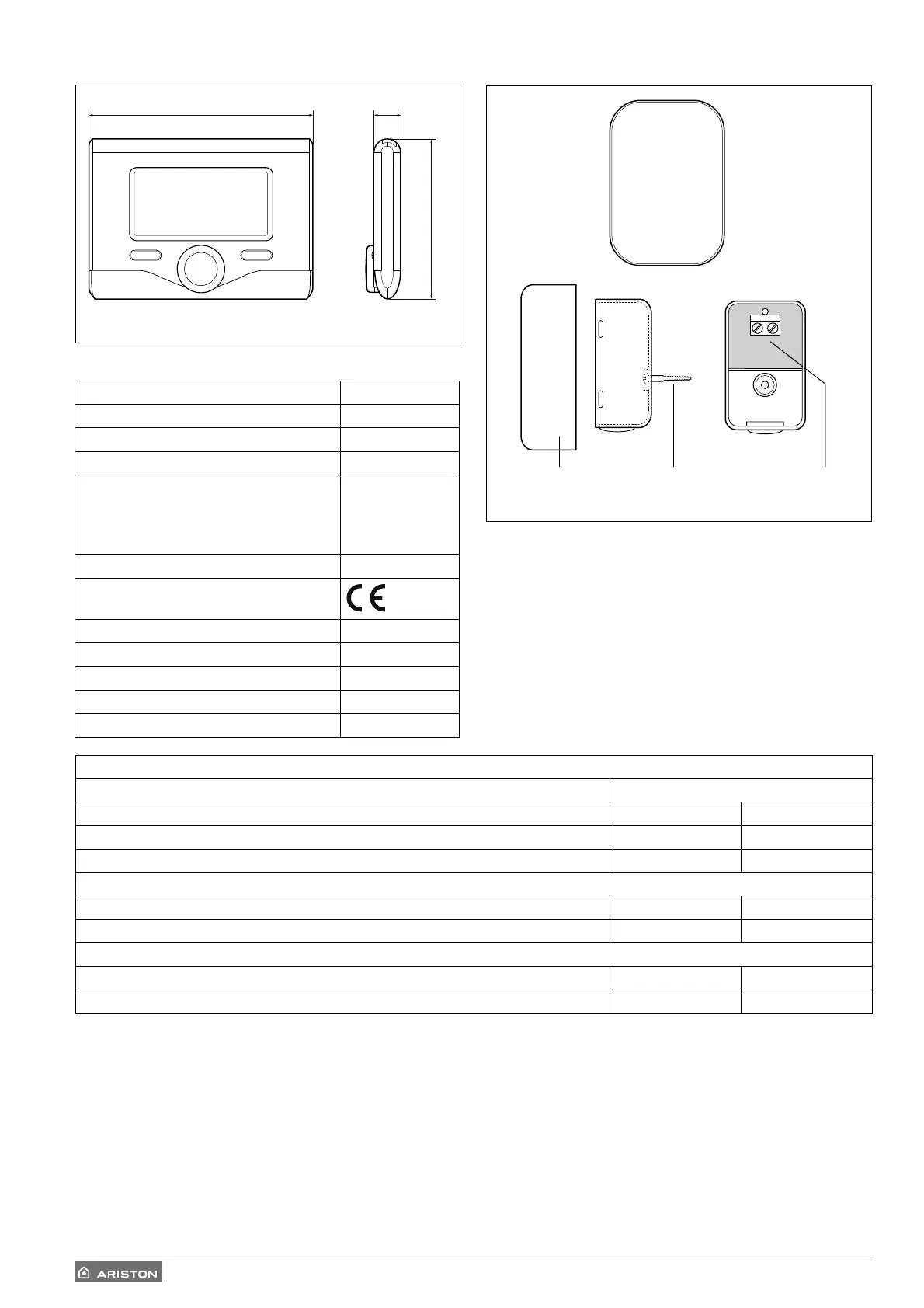
REMOTE CONTROL DEVICES OUTDOOR SENSOR
Position the outdoor sensor on the north-facing wall of the
building, at least 2.5 m from the ground and away from
direct sunlight.
Remove the cover (fi g. A) and install the sensor using the
rawl plug and screw provided (fi g. B).
Make the connection using a 2x0.5 mm
2
cable.
Maximum connection length 50 m.
Connect the wire to the terminal (fi g. C) by introducing it
from the lower part after creating a suitable passage.
Place the sensor cover back in the correct position.
AB C
PRODUCT FICHE
SUPPLIER’S NAME ARISTON
SUPPLIER’S MODEL IDENTIFIER Sensys Outdoor Sensor
Class of the temperature control V II
Contribution to seasonal space heating energy e ciency in % +3% +2%
Adding an outdoor sensor:
Class of the temperature control VI --
Contribution to seasonal space heating energy e ciency in % +4% --
In a 3-zones system with 2 room sensors
Class of the temperature control VIII --
Contribution to seasonal space heating energy e ciency in % +5% --
 Loading...