P/N PAK200929-ML • REV B • ISS 07OCT22 3 / 12
* Factory default setting.
** When BL INHIBIT link is fitted, BL+ cut line detection will not
report a Tamper to the control panel, however, it will still activate.
*** This cut-off time option intended for installation purposes only.
Hold Off Facility for Sound (BL+) and Strobe (FL+) Trigger
Inputs
A Hold Off facility is provided by links Blocage/BL INHIBIT
(BLi) and FL INHIBIT (FLi) to enable triggering of the sounder
and strobe from a control panel configured for positive hold-off
signalling (see Table 1 on page 2).
Links BLi and FLi connect internal pull-down resistors to the
BL+ and FL+ trigger inputs. When these links are FITTED, an
ALIM+/H+ (AUX+) voltage must be applied to BL+ or FL+ to
prevent (HOLD OFF) activation of the sounder or strobe
functions, respectively. Trigger by removing ALIM+/H+.
When the BL Inhibit or FL Inhibit links are NOT FITTED, the
control panel must supply a transition from ALIM+/H+ (AUX+)
to 0 V on BL+ or FL+ to trigger sound or flash.
SAD Mode
SAD (Sirène à Auto-Déclenchement) selects the response of
the sounder to various tamper (Auto-protection) conditions
according to Table 2 below.
Table 2: SAD Mode Auto-protection Condition
Tamper (Auto-
protection) condition
Removed from
mounting surface
Connection to BL+ is
cut (BL INHIBIT link
NOT fitted)
ALIM+/H+ or
ALIM−/H− power
connections cut
Connection to BL+ is
cut (BL INHIBIT link
fitted)
With SAD Mode OFF, the Auto-protection (AP) Output will still
open and signal an active tamper (Auto-protection) condition
back to the control panel under the conditions given in Table 2
above. If required, the sounder can be activated using a
normal sound trigger command from the control panel.
Sound Cut-off Timer
The AS700G3 sounder will automatically stop sounding after
the time period selected by the Sound Cut-off Timer link,
Table 1 on page 2, irrespective of the status of the sound
trigger (BL+) input. The 5 s option is provided to reduce
nuisance noise during testing.
Connections
Figure 3: Single AS700G3 connection
Figure 4: Multiple AS700G3 connection with tamper EOL
(1) Battery + wire (red)
(2) Battery − wire (black)
(3) Auxiliary power +
(9) Fault input
(10) Siren output
(11) Strobe output
(4) Auxiliary power 0V
(5) When Ring trigger is not
pulled to greater than
+8.5 V by the control panel
in standby mode, an
external 4K7 resistor
should be fitted between
ALIM+/H+ (AUX+) and
Siren output at the control
panel.
(6) Tamper input
(7) Tamper switch
(8) Fault input
(12) Programmable output
(13) Programmable output
(14) Control panel
(15) AS700G3 connected in
cascade. Note: CASC (LK1)
link must be cut in this siren.
See “Tamper circuit for single
or multiple cascade
installations” on page 2.
(16) AS700G3 connected as the last
one in the line
• BAT+: Positive connection to battery.
• BAT−: Negative battery connection. Connect black battery
lead after power is applied.
• ALIM+/H+: Permanent positive hold-off supply.
• ALIM−/H−: Permanent negative hold-off supply.
• AP(S): Connected to ALIM−/H− via WHITE/BLANC Link
(see Figure 4 for multiple sirens)
• AP(R): Auto-protection return connection to control panel.
(See Figures 3 and 4)
• FAUTE: Fault output: Volt free contacts
• BL+: Negative siren trigger, must be held to ALIM+/H+ in
standby mode.
• FL+: Negative strobe trigger, must be held to ALIM+/H+ in
standby mode.
• ING: Optional Engineer input connection for silent
operation during installation or maintenance. Apply +12 V
to initiate Engineer mode.
• TEST: Remote test trigger input (connect to ALIM+/H+ to
activate)
Note: If it is necessary to re-use a siren from cascaded to
stand-alone use (for example, white link has been cut), fit a
shorting link between AP(S) and ALIM−/H− terminals to restore
functionality.
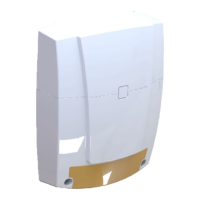
Installation and setup
Remove the screws (Figure 1, item 1) to open the siren
housing.
Select a suitable mounting position for the AS700G3 sounder.
Drill holes as required for fixing the backplate to the wall and
for cable entry to the rear of the unit.
Mounting holes are shown in Figure 2 as items 1, 2, and 5.
Use a screw in a centre top hole (Figure 2, item 2) to loosely
attach the siren to the wall.
Feed cables through central aperture.
Level the siren, and then tighten the screws (items 1, 2, and 5)
to secure position. Take care to apply only minimal force to
avoid tamper section breakout (Figure 2, item 5).
Check that the screw furthest to the right is well fixed to allow
the rear tamper to be broken. Take care not to break it during
assembly.
Connect the cables to the terminals. Form a loop with the rest
of the cable, directing it upwards and holding it in the clips
(items 4).
Position and close the terminal cover (item 6).
The cables from the control panel should pass through the slot
(item 7).