Do you have a question about the Aritech CS875 and is the answer not in the manual?
Essential and optional items for system installation.
Guidelines for safely wiring the CSx75 system to mains and phone networks.
Step-by-step guide for initial system setup and configuration.
Diagram illustrating the overall installation process flow.
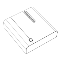
Wiring details for the CS-175 control unit.
Wiring details for the CS-275 control unit.
Wiring details for the CS-575 and CS-875 control units.
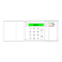
Basic steps required to install a keypad.
Instructions for physically mounting the keypad to a wall.
Diagram showing how to wire the keypad to the control unit.
Methods for connecting multiple keypads to the system.
Overview of zone wiring configurations.
How to wire zones using dual loop for alarm and tamper.
How to wire zones using single loop for alarm and tamper.
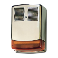
Wiring a sounder with End-of-Line protection.
Wiring diagram for the AS500 sounder.
Wiring diagram for the AS271 sounder.
Wiring diagram for the AS290/390 sounders.
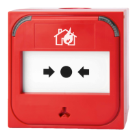
General considerations for wiring fire detectors.
Planning escape routes and safety measures in case of fire.
Explains the different types and wiring of outputs on CSx75 panels.
How the CSx75 automatically finds and stores connected modules.
Detailed steps for programming LCD keypads.
Detailed steps for programming LED keypads.
Explanation of system structure: modules, locations, segments, and bits.
Types of data (Numerical, Feature Selection) used in programming.
Using default programming for routine installations.
Steps to access the system's programming mode.
How to choose which module to program.
Procedure to reset the controller to factory default settings.
Setting the appropriate country code for system defaults.
Instructions for programming using an LED keypad.
Instructions for programming using an LCD keypad.
Overview of using PC software for programming.
How to wire the RS232 cable for PC connection.
Steps for programming using up/download software.
Explanation of LED indicators in master mode.
How system status is displayed in master mode.
Configuring DIP switches for the RX8i4-16i4 module.
Understanding the LED indicators for module status.
Wiring instructions for the RX8i4-16i4 module.
Procedures for programming the wireless receiver module.
Configuring DIP switches for RX8w8-16w8 receivers.
Understanding LED indicators for module status.
Wiring instructions for RX8w8-16w8 receivers.
Procedures for programming RX8w8-16w8 wireless receivers.
Configuring DIP switches for the CS216 zone expander.
Wiring instructions for the CS216 hardware zone expander.
Programming the CS216 zone expander.
Definition and explanation of CS534 audio board features.
Wiring instructions for the CS534 audio board.
How the CS534 operates during two-way sessions.
Explanation of CS534 operation in line-hold or call back modes.
Procedures for programming the CS534 audio board.
Configuring DIP switches for the CS507 output expander.
Wiring instructions for the CS507 output expander board.
Programming the CS507 output expander configuration.
Wiring instructions for the CS586 RS232 interface module.
General operating procedures for the CS586 interface.
Programming the CS586 RS232 interface parameters.
List of module numbers for different keypads.
List of module numbers for CS216 expanders.
Module numbers for the CS507 output module.
Module numbers for wireless receivers.
Module numbers for RX8I4 wireless receivers.
Technical details and configurations for keyswitch zones.
| Brand | Aritech |
|---|---|
| Model | CS875 |
| Category | Security System |
| Language | English |