507405-05Page 30 of 72 Issue 1621
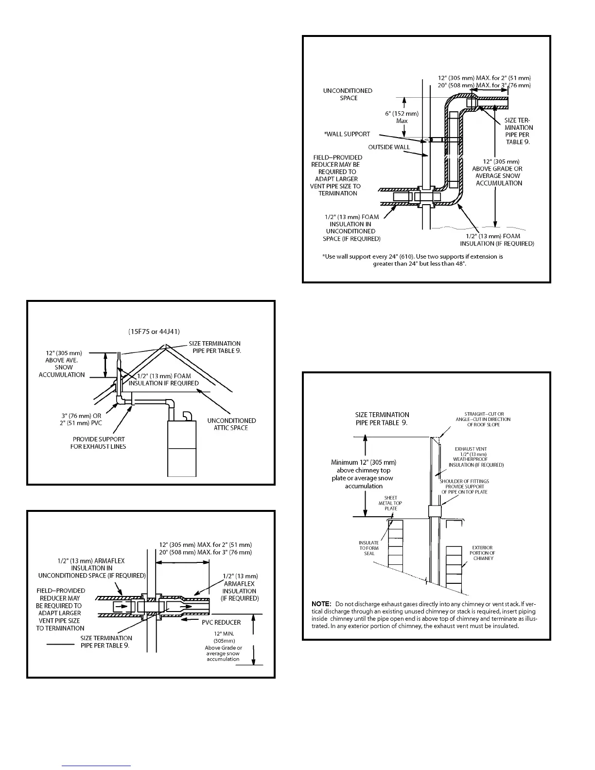
Details of Exhaust Piping Terminations for Non-Direct
Vent Applications
Exhaust pipe may be routed either horizontally through
an outside wall or vertically through the roof. In attic or
closet installations, vertical termination through the roof is
preferred. Figures 39 through 42 show typical terminations.
1. Exhaust piping must terminate straight out or up as
shown. The termination pipe must be sized as listed
in Table 9. The specied pipe size ensures proper
velocity required to move the exhaust gases away from
the building.
2. On eld supplied terminations for side wall exit, exhaust
piping may extend a maximum of 12 inches (305 mm) for
2” PVC and 20” (508 mm) for 3” (76 mm) PVC beyond
the outside wall. See Figure 40.
3. If exhaust piping must be run up a sidewall to position
above snow accumulation or other obstructions, piping
must be supported every 24” (610 mm) as shown in
Figure 41. When exhaust piping must be run up an
outside wall, any reduction in exhaust pipe size must
be done after the nal elbow.
Figure 39
Non-Direct Vent Roof Termination Kit
Figure 40
Non-Direct Vent Field Supplied Wall Termination
Non-Direct Vent Field Supplied Wall Termination
Extended
Figure 41
Figure 42
Non-Direct Vent Application Using Existing Chimney