8
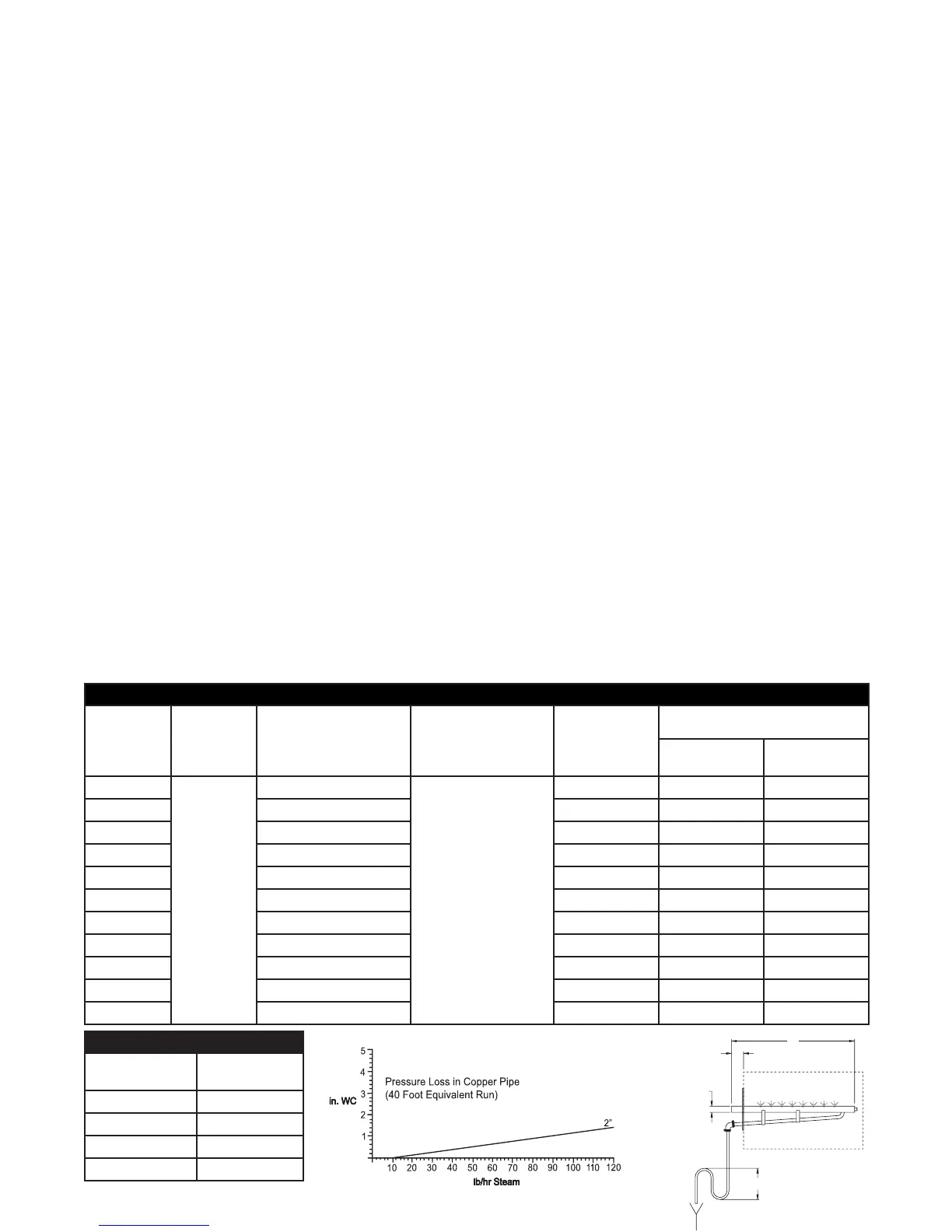
Table 8-1. Dispersion Tube Length
Model
HC6100,
HC6100DI
Model
HC6100,
HC6100DI
“D” Dia.
Model HC6300,
HC6300DI, HC6500,
HC6500DI, HC6700,
HC6700DI
Model HC6300,
HC6300DI, HC6500,
HC6500DI, HC6700,
HC6700 DI “DL” Dia.
Steam Disp. Tube
Length “L”
mm (in)
Duct Width
Minimum
mm(in)
Maximum
mm (in)
D-1
1-1/2”
DL-1
2-3/8”
305 (12) 280 (11) 406 (16)
D-1.5 DL-1.5 457 (18) 432 (17) 559 (22)
D-2 DL-2 610 (24) 584 (23) 864 (34)
D-3 DL-3 914 (36) 889 (35) 1168 (46)
D-4 DL-4 1219 (48) 1194 (47) 1473 (58)
D-5 DL-5 1524 (60) 1499 (59) 1778 (70)
D-6 DL-6 1829 (72) 1803 (71) 2083 (82)
D-7 DL-7 2133 (84) 2108 (83) 2388 (94)
D-8 DL-8 2438 (96) 2413 (95) 2692 (106)
D-9 DL-9 2743 (108) 2718 (107) 2997 (118)
D-10 DL-10 3048 (120) 3023 (119) 3302 (130)
Duct Steam Distribution
1. The dispersion tube should be proper length. Verify correct size from Table 8-1.
2.Installdispersiontube(s)horizontallyinductsoholesfaceupward.Airflowmustbeverticalupor
horizontal.Donotrestrictductwithaheightof200mm(8”)orless.Installationsover10m/s
(1800FPM)airvelocityarenotrecommended.Consultfactoryifairflowisverticaldownorair
velocityisover10m/s(1800FPM).Donotinstallinductedsystemswithstaticpressureexceeding
150mm(6”),wc.Airflowshouldbeaminimumof250FPMforinstallationsusingdispersiontubing.
Consult factory if velocity is below recommended level.
3.Thedispersiontube(s)shouldbelocatedupstreamofastraightductrun,withoutobstructions,3m
(10feet)ormoreinlength.Consultthefactoryifthisdistanceisnotavailable.
4. Use the template provided to cut dispersion tube installation holes. Fasten the mounting plate to
ductwithsheetmetalscrews.Ifthedispersiontubeis900mm(35”)orlonger,supportthefar
end with threaded rod or similar means.
5. Note:Forsteambeinggeneratedfromadeionized(DI)orreverseosmosis(RO)watersource,the
useof50mm(2”)insulatedstainlesssteelpipinginlieuofcopperisrequired.Pipeusedforsteam
dispersion piping must be oil and contaminate free. Premature element failure could result if oils or
contaminatesarepresent.Contactthefactorywithquestions.Connectdispersiontube(s)to
HumidiCleantankusing50mm(2”)nominalinsulatedcopperpipeandhosecuffsprovided.Wedo
not suggest steam distribution piping of field supplied rubber based compounds to be used for any
HumidiCleanapplication.Pitchpipebacktounit25mm(1”)perfoot.Thesteampipemustbefree
of kinks and sags to allow for gravity drainage of condensate. Maximum pipe run distance from
tanktodispersiontubeis12m(40feet)equivalentpipinglength.Avoidexcessiveuseofelbowsor
45°changesindirection.A“P”trapshouldbeinstalledevery6m(20feet),ofpipingrunorat
the bottom of vertical runs that cannot drain back to the tank. See Fig. 5-1 or 5-2 for piping detail.
6.Ifductstaticpressurepluspipingbackpressureisgreaterthan0.5inHG(6”WC),pleaseconsult
thefactory.(SeeFigure8-1forbackpressureinpiperun.)
D
2
L
6" Min. Water Seal
Figure 8-2
Figure 8-1
Table 8-2.
Fitting Style
Equivalent Linear
Piping (feet)
2” - 45° Elbow 2.8
2” - 90° Elbow 5.5
2” - 90° Long Elbow 3.5
2” - Tee 12