48
g. When operation has finished, close the “SAM-BA” window first, and then click the icon “remove
the USB hardware” to disconnect the link between computer and board. After reminder by
system, disconnect the power supply from breaker and pull out the USB cable.
h. The soft refresh of HC-6000 is complete, restart the unit.
Introduction to Communications
Modbus Protocol Setup
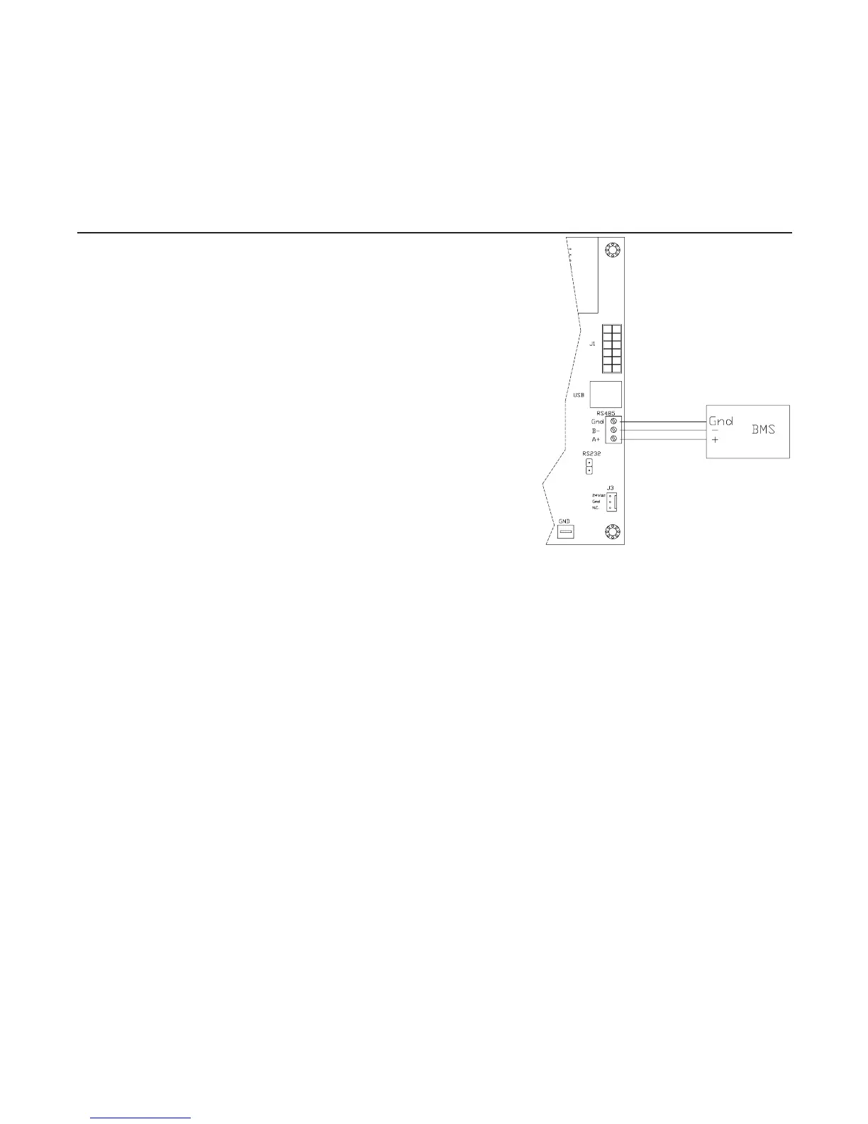
1. Wire to the RS-485 port, following Figure 48-1.
2. Make sure that all proper connections are made and that
the installation instructions that start on page 6 have been
adhered to. Power unit on.
3. Once unit is on go to “Operation Setup” and verify the
following data:
a. Network Setup – Enabled
b. Secondary ID – Default is Secondary ID 1, but set to fit
your system
(Ifusingmultipleunits,eachunitshouldhaveadifferent
SecondaryID)
c. Communication Type – Modbus
(WhenthescreenshowsModbushitentertogoto
advancedsettings)
i. Baudrate – Default is 9600, but set to match
your system
ii. Parity – Default is Even Parity, but set to match your system
iii.StopBit–Defaultis1Bit(s),butsettomatchyoursystem
4. Now the changes to the actual unit are complete use Table 51-1 Modbus Variants List to help
set up the required points in the Building Management System.
LonWorks Protocol Setup
1. Attach protocessor into upper right hand corner of main pc board. The ethernet connection
shouldbegoingtotheinsideoftheboard.(SeeFigure49-1)Makesurethatallpinsareseated
properly and making a good connection.
2. Landtwo-wireBMSsystemtowireterminalonprotocessor.(SeeFigure49-1)
3. Make sure that all proper connections are made and that the installation instructions that start
on page 6 have been adhered to. Power unit on.
4. With the humidifier powered on connect to the protocessor via the ethernet port through RUInet
(seeChangingProtoCessorConfigurationFile).Typicallythisisneededifthedefaultvalues
need to be changed or if there is more than one unit operating in the system on the same pro-
tocol that would require a Node ID change. Note that any time the system loses power the unit
will divert back to the default settings.
5. When the humidifier is powered access the Operation Setup menu through the front display
and set the following information:
a. Communication Type – PSP
b. Secondary ID - 1
6. Now the changes to the actual unit are complete use Table 52-1 LonWorks Variants List to help
set up the required points in the Building Management System. The .xif file is available and can
Figure 48-1. Modbus RS485 Wiring