- 9 -
Owner’s manual
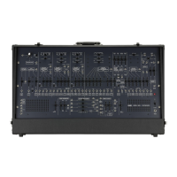
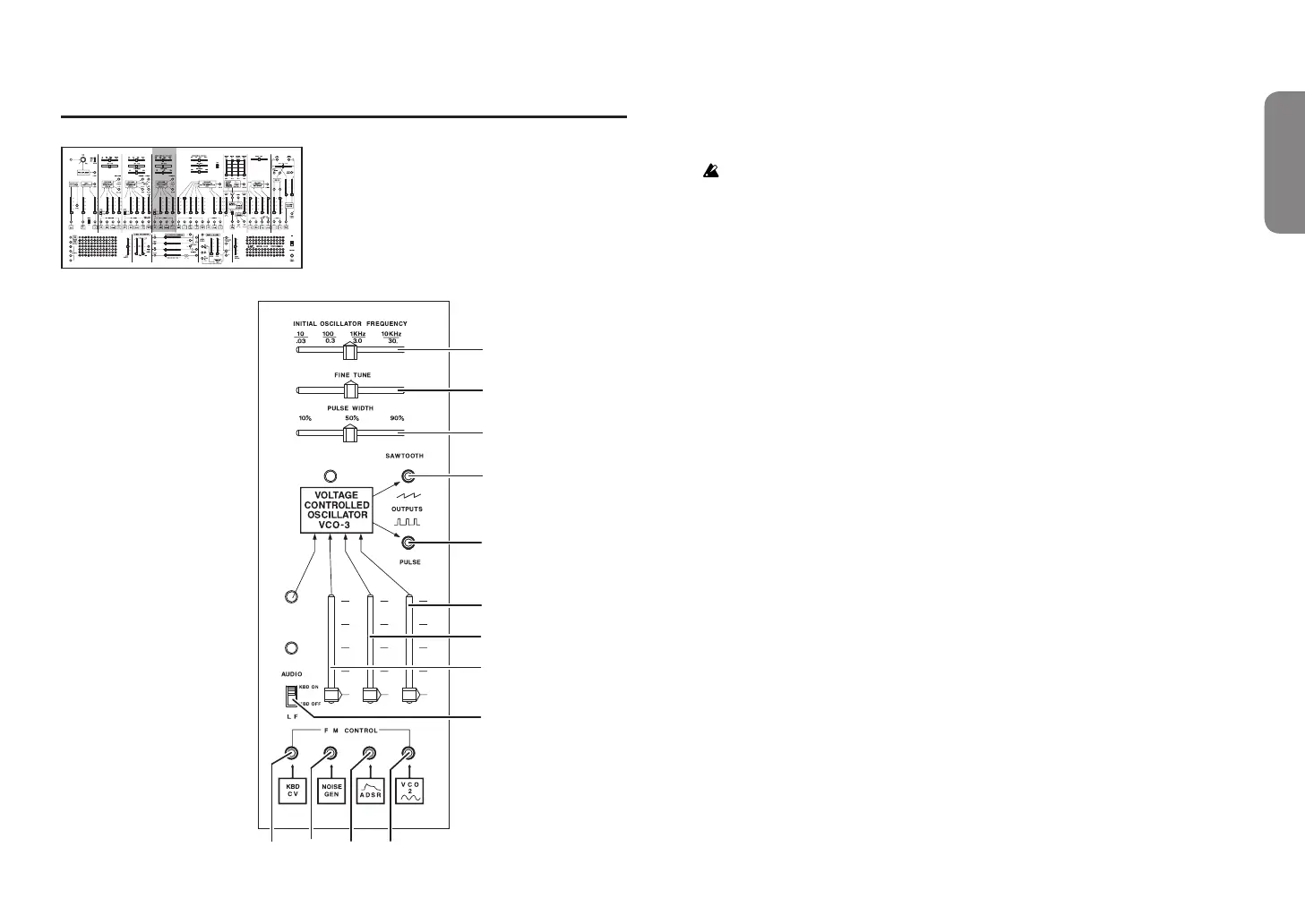
Front panel (VCO-3 section)
INITIAL OSCILLATOR FREQUENCY INITIAL OSCILLATOR FREQUENCY
a
b
d
c
l
m
h
i
j
k
e
f
g
VCO-3 (Voltage Controlled Oscilator 3)
a. INITIAL OSCILLATOR FREQUENCY slider ...................[10(.03)Hz…10K(30.)Hz]
Broadly adjusts the VCO-3 pitch.
The frequency range is an approximate value.
b. FINE TUNE slider
Finely adjusts the VCO-3 pitch.
c. PULSE WIDTH slider ....................................................................... [10%…90%]
Adjusts the duty cycle of the VCO-3 pulse wave.
d. CV input 1 jack
This is the pitch CV input jack for VCO-3. The KBD CV is internally connected.
e. CV input 2 jack
This is the pitch CV input jack for VCO-3. The noise generator is internally
connected.
f. CV input 3 jack
This is the pitch CV input jack for VCO-3. The ADSR is internally connected.
g. CV input 4 jack
This is the pitch CV input jack for VCO-3. The sine wave of VCO-2 is internally
connected.
h. AUDIO/LF select switch ....................................................... [KBD ON, KBD OFF]
Selects whether to use VCO-3 as an audio signal or as an LFO. When used as an
LFO (KBD OFF), the CV from the keyboard is no longer input to VCO-3.
i. CV input level 2 slider
Adjusts the signal level of VCO-3 CV input 2.
j. CV input level 3 slider
Adjusts the signal level of VCO-3 CV input 3.
k. CV input level 4 slider
Adjusts the signal level of VCO-3 CV input 4.
l. SAWTOOTH output jack
Outputs the sawtooth wave of VCO-3.
m. PULSE output jack
Outputs the pulse wave of VCO-3.
 Loading...