EXPERIMENT 1. RING
MODULATION
Lower ihe blue and
green sliders
under the AUDIO
M!XER BOX, and raise the white slider
sgaift.
Changs the
position
of th& slide switch under the while slider
front
Noise to RING MOD.
Make sure
thai the PHASE SYNC
switth for VCO 2 is off. Play a
few notes
on
the
keyboard
and IJEEen
to
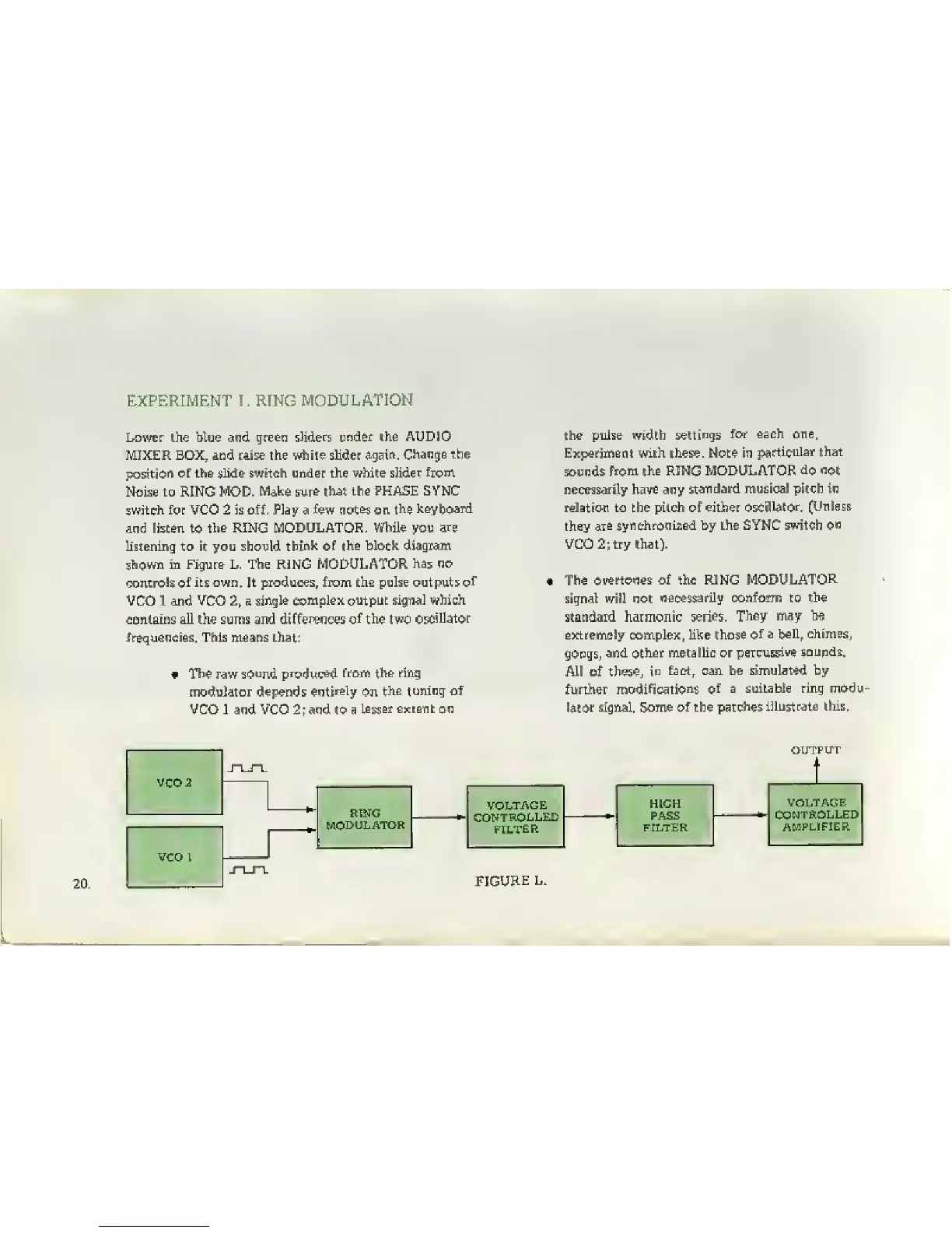
the RING MODULATOR. While you ar«
hstening to it you
should
think
of
the block diagram
shown in Figure L. The RING MODULATOR
has no
oontroSs of
its own. It
piroduoes,
from the pulse outputs
of
VCO 1 and VCO
2f
a
single complex output signal which
contains all the sums and
differences of
thie
two
oscillator
frequencies. This m'Satis that:
« The raw
sound produced
from the ring
modulator depends
entirely
on
the tuning of
VCO 1 and VCO
2;
and to a
lesser extant on
the pulse width
settings
for each one.
Experiment with these. Note in
partitular that
sounds
from the RING MODULATOR
do
not
necessarily
have
any
standard musical pitch in
relation to the pitch of either
oscillator.
[Unless
they
ate
synchronised by the SYNC
switch on
VC0 2;Lry that).
The
overtones of the RING
MODULATOR
signal will not
necessarily conform to the
standard harmonic
series.
They may be
extremely complex, like those
of
a bell, chimeSj
gongs,
and other metalhc or
percussive
sounds.
All of
these, in
fact, can he simulated by
further
modifications of
a suitable ring modu-
i^Eor
signal. Some of the patches
iEustrata
this.
VCO 2
J-LTL
KING
MODULATOR
VCOl
J-LJ-L
VQLTAGE
CONTROLLED
FILTER
HICK
PASS
FtLTEK
VOLTAGE
CONTROLLED
AMPLIFIER
 Loading...