Chapter 5: Installing and Connecting your Telephony Modem
Release 8 STANDARD 1.1 August 2016 Touchstone TM804G Telephony Modem User Guide
© 2011-2016 ARRIS Enterprises LLC. All Rights Reserved. 25
6. Link: indicates Ethernet connectivity between the Telephony Modem and computer. it
may be yellow or green to indicate the connection speed.
7. Online: indicates internet data transmission status.
8. US: indicates upstream connectivity. It may be yellow or green to indicate the connection
speed.
9. DS: indicates downstream connectivity. It may be yellow or green to indicate the
connection speed.
10. Power: indicates whether AC power is available to the unit.
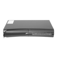
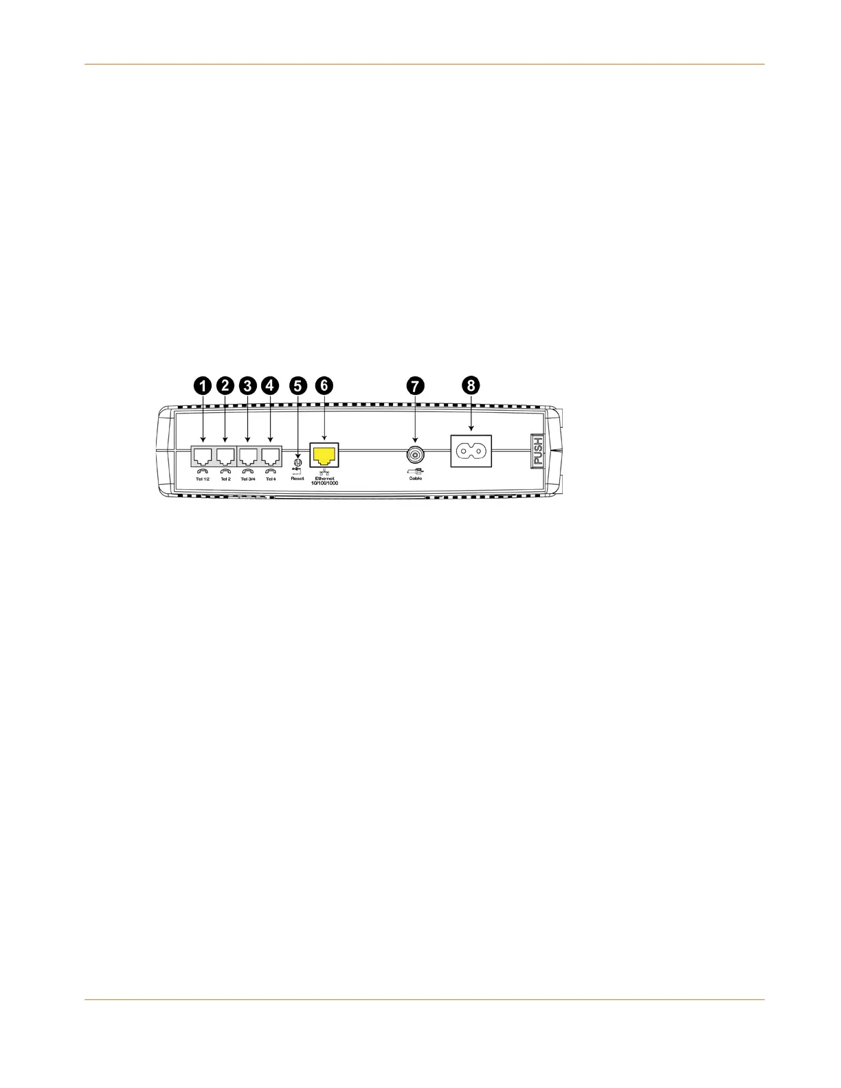
Rear Panel
The rear of the Telephony Modem has the following connectors and controls.
1. Tel 1/2: connector for the first phone line (or both lines of a 2-line phone).
2. Tel 2: connector for the second phone line.
3. Tel 3/4: connector for the third phone line (or both lines of a 2-line phone).
4. Tel 4: connector for the fourth phone line.
5. Reset button: resets the Telephony Modem as if you power cycled the unit. Use a pointed
non-metallic object to press this button.
6. Ethernet: connector for use with a computer LAN port.
7. Cable: connector for the coaxial cable.
8. Power: connector for the power cord.
Selecting an Installation Location
There are a number of factors to consider when choosing a location to install your Telephony
Modem:
Is an AC outlet available nearby? For best results, the outlet should not be switched and
should be close enough to the Telephony Modem that extension cords are not required.
Is a cable jack available? For best performance, keep the number of splitters between the
jack and cable drop to a minimum. Each splitter attenuates (reduces) the signal available
to the Telephony Modem. A large number of splitters can slow down the Internet
connection and even affect your telephone service.
Can you easily run cables between the Telephony Modem’s location and the phones?