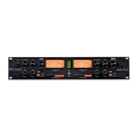
7
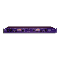
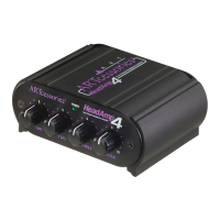
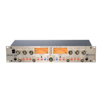
B. +48V Switch: The +48 Volt phantom power (when ena-
bled) is supplied to pins 2 and 3 and pin 1 acts as the
ground return. Do not lift pin 1 when using phantom power.
C. INPUTS: These potentiometers independently vary the in-
put gain for the Left and Right Channels 1 thru 4.
D. OUTPUT LEVEL (OUT 1/2): This potentiometer varies the
output gain for channels 1 and 2.
E. Input Monitor: When the switch is engaged, a user can
monitor the input signal from the ¼-inch headphone jack.
F. Headphone LEVEL (OUT CH3/4): This potentiometer
allows the user to adjust the gain to the Headphone out
jack.
G. Headphone Jack: Access point for monitoring.
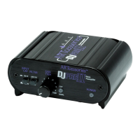
H. USB Jack: Interface and unit power.
I. MIDI INPUT/MIDI OUTPUT: Midi Access points.
J. Main Output: Analog outputs.
K. Left and Right “Combo” jacks on the rear allow for either
XLR or ¼-inch TRS input connections. You can use an un-
balanced or balanced plug with this connection.
CONTROLS and OPERATION
The ¼-inch output Jacks have an output impedance of 300
Ohms and a maximum output level of +8dBu (CH1/2) which pro-
vides a clean a signal for long cable runs. Normally you would
use this output to go directly into a power amplifier, powered

 Loading...